
Biosensor circuit

The circuit design process began with the selection of an appropriate software tool that facilitates schematic creation and PCB layout. The chosen software allows for intuitive manipulation of components and wiring, enabling the designer to effectively visualize and implement the circuit's functionality. The design incorporates essential elements such as resistors, capacitors, and operational amplifiers, which are critical for the intended application.
The inclusion of battery switches is a key feature, providing the ability to easily disconnect the power source when the circuit is not in use, thereby extending battery life and enhancing safety. The DIP switch serves as a versatile control mechanism, allowing for the adjustment of resistance values in the circuit. This adaptability is crucial for testing and optimizing circuit performance under various conditions.
Once the schematic was finalized, the design was prepared for manufacturing. The Biomedical Technology Workshop was engaged for the fabrication of a prototype case, which serves not only a protective function but also contributes to the overall design aesthetics. Careful consideration was given to the case design to ensure it is visually appealing while maintaining functionality. This prototype will facilitate further testing and validation of the circuit's performance before proceeding to the PCB stage, thus ensuring that all design objectives are met effectively.This week was spent completing a number of different objectives. Firstly, the software was downloaded to design the schematic for the circuit to be translated onto a PCB. Much of the week was spent doing tutorials and learning the user interface to make a nice circuit. Also, the circuit, complete with switches for the batteries as well as a DIP switch to control resistance, was given to the Biomedical Technology Workshop for manufacturing into a case. This will serve as the first prototype (not the PCB), and steps were taken in order to ensure it was pleasing to the eyes.
🔗 External reference
Related Circuits
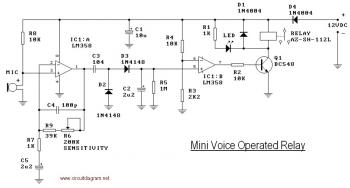
This circuit diagram illustrates a voice-operated relay, which functions similarly to a sound-activated switch circuit. It activates and deactivates the switch based on sound input. The output switch of this circuit is controlled by a relay. The release time...
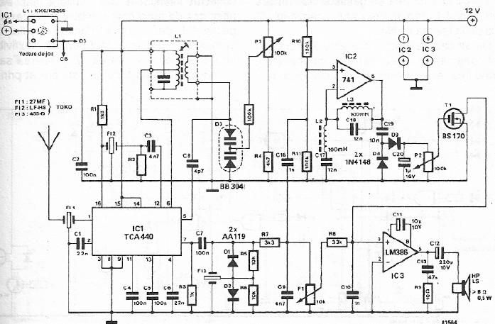
A simple FM CB radio receiver can be constructed using the electronic diagram provided. This FM CB radio receiver circuit utilizes a TCA440 integrated circuit and operates at an intermediate frequency of 455 kHz. The input filter is a...
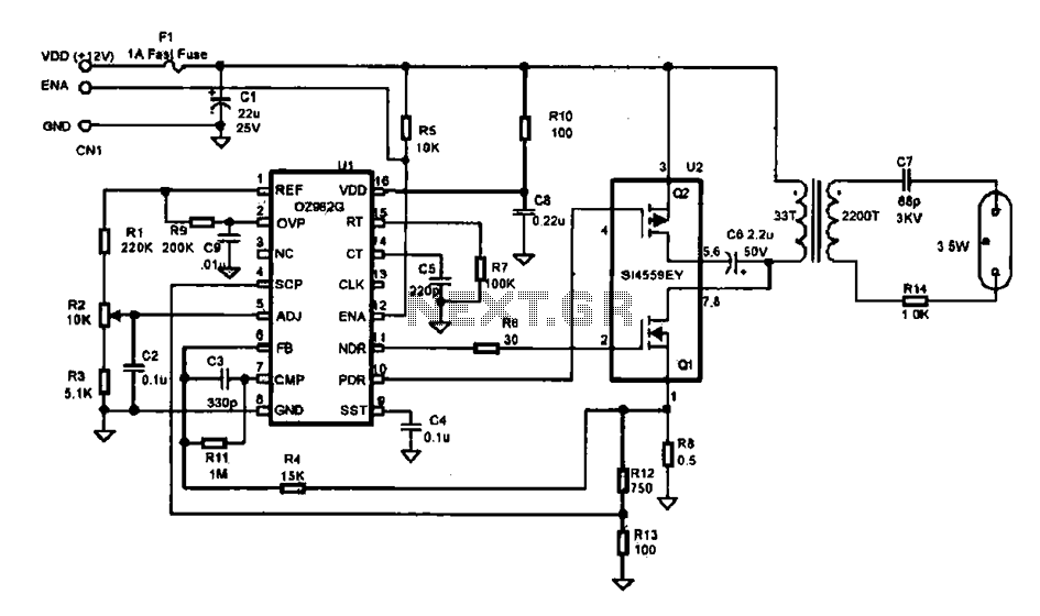
This document describes an efficient inverter control circuit designed for use as an LCD backlight power supply. The circuit is primarily managed by the chip UL (02962G), which interfaces with a driving field-effect transistor (U2), a voltage transformer, the...
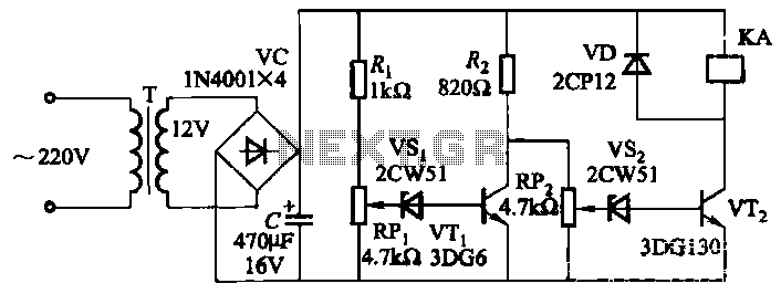
The circuit employs a transistor control mechanism. When the grid voltage is within the normal range, relay KA is activated, supplying power to the load. If the grid voltage falls below the minimum allowable threshold (adjustable via potentiometer RPz)...
A type of relaxation oscillator comprising two stages that are interconnected such that the input of one stage is derived from the output of the other. This configuration essentially consists of two amplifiers cross-coupled with regenerative feedback in its...
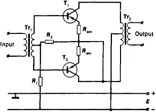
An amplifier is a device that accepts a varying input signal and produces an output signal that varies in the same way as the input but has a larger amplitude. The input signal may be a current, voltage, mechanical...