
birdie doorbell circuit

This doorbell circuit utilizes a basic configuration to generate sound through a loudspeaker, with the primary control mechanism being an NPN transistor. The design is straightforward, allowing for flexibility in component selection and adjustments based on user preferences. The starting point for the resistor P1 at 220 Ohms provides a baseline for tuning the circuit for optimal sound output.
The bell transformer (L1) plays a crucial role in the circuit, as it converts the low voltage from the power source to a higher voltage suitable for sound generation. In cases where a bell transformer is not available, a 9-volt battery or wall adapter can be employed, ensuring that the circuit remains functional. The inclusion of diode D1 is vital for safeguarding the circuit against incorrect polarity connections, which could potentially damage the components.
The use of a general-purpose PNP transistor (T1) allows for versatility in component selection, as various PNP transistors can be utilized without significant impact on circuit performance. The second transformer (L2) sourced from an AM radio contributes to the sound modulation, and experimentation with different transformers is encouraged to achieve the desired audio effect.
The loudspeaker selection is also important; an 8 Ohm speaker rated for at least 200 milliwatts ensures adequate sound output without distortion. A 2-watt speaker is a suitable choice, providing ample power handling for the circuit's requirements. Overall, this doorbell circuit design allows for customization and experimentation, making it an engaging project for electronics enthusiasts.This is a design circuit for a doorbell. This circuit can produces a sound like bird sound. This circuit controlled by transistor NPN. This is the figure of the circuit. The operation of the circuit is beginning when P1 is of experimental value. Start with 220 Ohms or so and modify to suit your needs. The transistor is a general purpose kind and i s not critical, almost any PNP type will work. L1 is a bell-transformer which is usually already present in the house. If you wish, you could use a battery instead of the bell transformer. Just hookup a 9-volt battery (or wall adapter)to points `A` and `B` (A=+) the diode (D1) is to protect the circuit from accidental polarity reversal and is optional, but required as a rectifier for use with the bell transformer. The transistor T1 is a General Purpose PNP transistor and probably anything will work. L2 comes out of an old am transistor radio. They look like miniature transformers and are usually colored red or green. You have to fiddle with different transformers as the sound can vary depending on the value. The loudspeaker is a 8 Ohm type and must be larger than 200milli-Watt. I used a 2Watt type, but anything over 0. 2W will do. 🔗 External reference
Related Circuits
The video master comprises a series of converters that allocate all video sources to unused UHF channels. These channels are then combined with standard TV channels, whether terrestrial or cable, into a single cable. This single cable can subsequently...
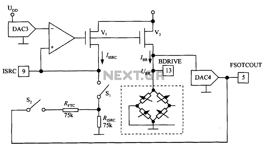
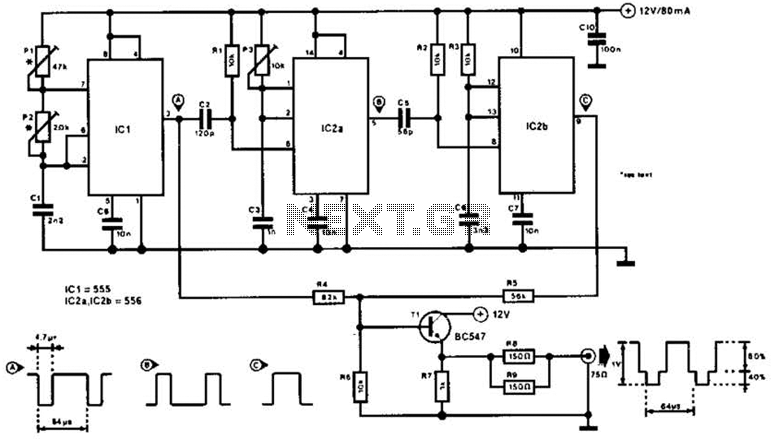
The excitation circuit for the digital pressure signal conditioner MAX1458 is illustrated. The output DAC3 is utilized to adjust the sensor excitation current (IBR), enabling full-scale fine calibration. The reference current (IISRC) is determined by the resistor RISRC and...
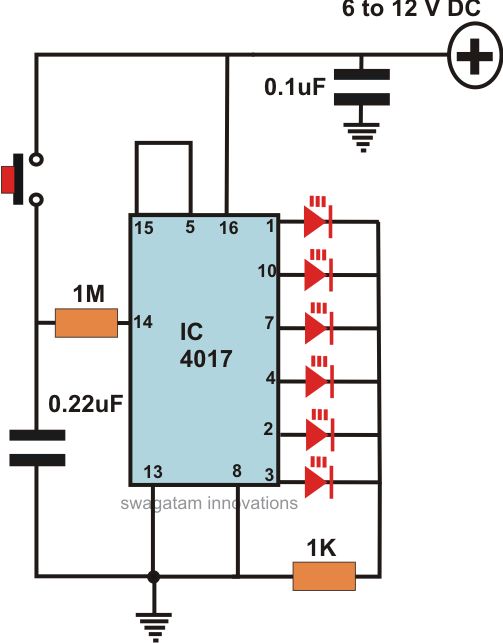
This article offers a circuit diagram and a discussion on CMOS logic and IC layout for creating a set of attention-getting LED running lights. It details a simple sequential LED flasher or light chaser that can be built, including...
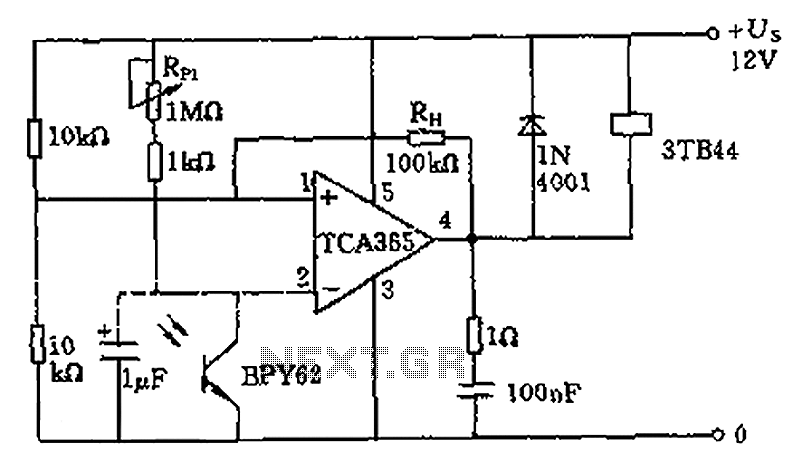
A bridge input circuit utilizing a phototransistor BPY62 and a power operational amplifier is capable of controlling power loads up to 8.5 kW. It features a voltage divider composed of two 10 kΩ resistors, creating a midpoint connection. The...
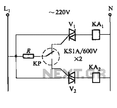
To prevent the failure of electric contact pressure thermometer contacts due to singeing, it is advisable to enhance the contacts, as illustrated in Fig. 11-60. Specifically, the output termination table for DC control utilizes two two-way thyristors or a...
This circuit utilizes the widely available LM3914 integrated circuit (IC). The IC is straightforward to operate, does not require external voltage regulators due to its built-in voltage regulation feature, and can be powered from nearly any voltage source. The LM3914...