
Avoid contact thermometer circuit

In this circuit configuration, the electric contact pressure thermometer serves as a critical component for temperature measurement and control in various applications. The enhancement of the contacts is vital to ensure reliability and longevity, particularly in environments where high temperatures can lead to contact singeing.
The use of thyristors or triacs in the output termination table allows for effective control of the load, with the choice between DC and AC control depending on the specific application requirements. Thyristors are suitable for DC applications, providing robust switching capabilities, while triacs are preferred for AC applications due to their ability to conduct current in both directions.
The electric contact pressure thermometer contacts are designed to trigger the gate of the thyristor, enabling it to turn on and allow current to flow to the load. This configuration ensures that the thermometer can accurately control the temperature by modulating the power delivered to the heating element or other devices.
In summary, the integration of enhanced contacts with thyristor or triac control mechanisms provides a reliable solution for temperature management, minimizing the risk of singeing and ensuring consistent performance in various industrial and commercial applications.In order to prevent electric contact pressure thermometer contacts singeing failure, the best way is to work to improve the contacts, as shown in Fig. 11-60. Namely (DC control) output termination table two two-way thyristor or triac (AC control), electric contact pressure thermometer contacts only control the thyristor gate.
Related Circuits
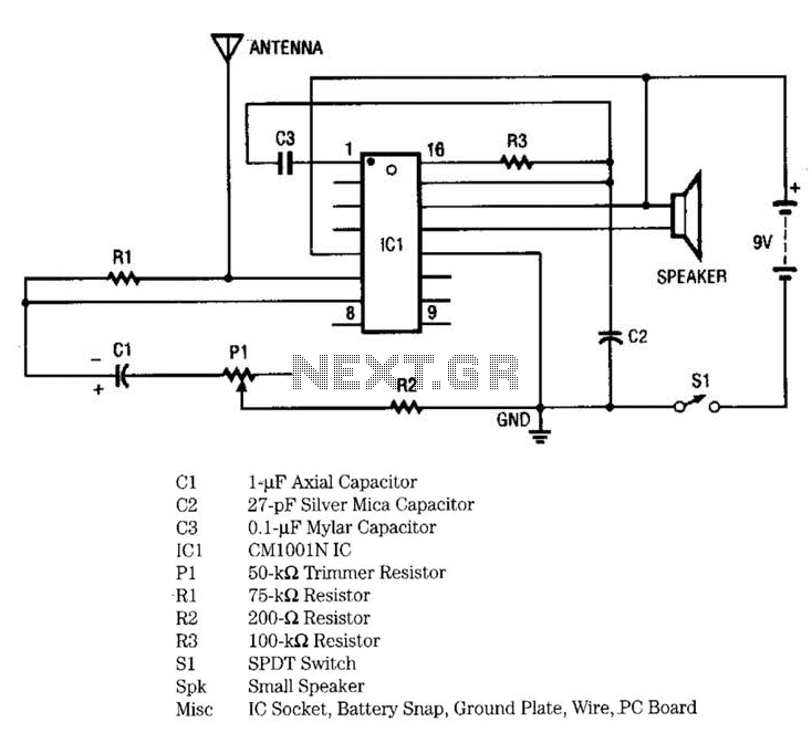
IC1 includes multiple oscillators and an amplifier. The low-frequency audio signal oscillator provides an input to the amplifier. This signal is the audio tone that is amplified and subsequently delivered to the speaker by the amplifier. The high-frequency oscillator...
The following circuit illustrates a Water Level Detector Circuit Diagram. This circuit is based on the PIC12F683 microcontroller. Features include the ability of the PIC microcontroller to enter a sleep mode. The Water Level Detector Circuit utilizing the PIC12F683 microcontroller...
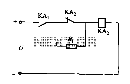
A DC relay or contactor is utilized to enhance the excitation pull-in and release mechanisms in a circuit. The relay circuit, as depicted in Figure 6-28, facilitates improved return line efficiency. When the control relay KAi is activated, its...
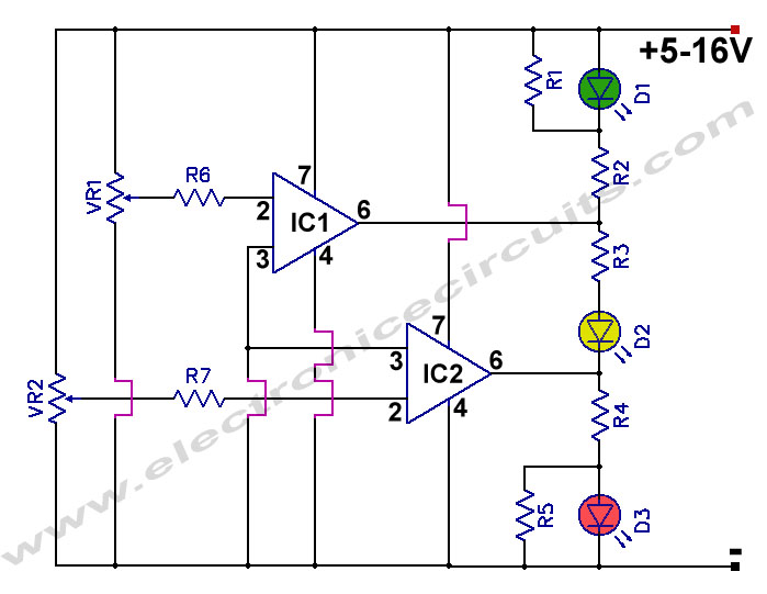
12V Battery Charge Nominal Discharge (Low) Indicator Circuit. This circuit monitors car battery voltage and provides an indication of nominal levels. The 12V Battery Charge Nominal Discharge Indicator Circuit is designed to monitor the voltage levels of a car battery...
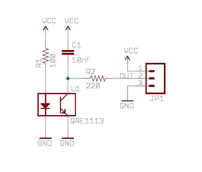
A real-time clock turns off the counter at night to conserve power. When a bee crosses under the LED, the light is reflected back to the sensor, which is a phototransistor, and triggers a digital input to the Arduino...
This project features a schematic for a touch alarm circuit. The circuit is highly sensitive and activates a piezo buzzer or any other type of buzzer, along with an LED, for a predetermined duration when a metal plate is...