
Boat alarm

The circuit in question is designed as a security mechanism, utilizing resistors R1 and R2 to maintain a stable connection to a power source and ground. In a typical configuration, R1 is connected to a +12 V supply, while R2 is grounded. The removal of either resistor disrupts the circuit's integrity, effectively signaling an unauthorized tampering attempt.
When R1 or R2 is removed, the circuit detects the change in resistance and triggers an alarm system. This alarm is programmed to activate for a duration of about five minutes, serving as a deterrent to potential intruders. The design relies on the principle of voltage division and current flow, where the resistors play a crucial role in maintaining the circuit's normal operation.
In practical applications, this circuit can be integrated into various security systems, including home alarm systems, vehicle anti-theft devices, or any application requiring a hidden security feature. The alarm's five-minute activation period provides sufficient time for the property owner or security personnel to respond to the breach, ensuring a proactive approach to security management.
This schematic can be further enhanced with additional features such as a timer reset mechanism, a notification system that alerts the owner via mobile or SMS, or integration with surveillance cameras for visual confirmation of the alarm trigger. The overall effectiveness of this circuit relies on its simplicity, reliability, and the element of surprise it offers against potential threats.Removing R1 or R2 from the circuit the potential thief breaks a hidden wire that connects R1 to +12 V and R2 to ground) Activates the alarm for about five minutes.
Related Circuits
This circuit is a simple wire loop alarm that can be used in doorways, hallways, or any other place the tripwire will be broken by intruders. The circuit has a built-in siren, but it can be replaced by a...
This circuit is designed to detect whether the load of a battery charger or plug-in adapter is properly connected. The load may consist of a set of batteries needing charging or any other device that operates on low DC...

The schematic in question is unconventional in design and should not be used as a model for beginners in electronics. A significant drawback of this basic circuit is that the alarm is triggered only when the light beam on...

The circuit of a loop sensor-based simple security alarm is described here. The sensor loop consists of a short length of thin enamelled copper wire. The loop sensor security alarm operates on the principle of detecting interruptions in the circuit...
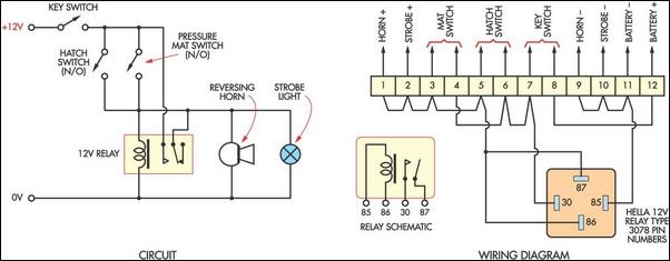
This cost-effective burglar alarm utilizes a 12V strobe light and a truck reversing horn as the visual and audible alarm outputs. The alarm mechanism consists of a 12V horn relay and several pressure mat switches. This straightforward design ensures...

This circuit diagram represents a smart car alarm timer. This design is more advanced compared to traditional car alarm systems. When activated, the alarm remains active for 80 seconds, following an initial delay of 15 seconds. The smart car alarm...