
Boba Fett project movement

The described timer circuit is integral for controlling a servomotor's movement with precision. The timer's ability to generate a consistent 20 ms period allows for fine control over the output signal frequency, which is essential for servomotor applications. The division of this period into 256 steps through an 8-bit variable provides a high resolution for position control, enabling the servomotor to respond accurately to user inputs.
The duty cycle variable plays a crucial role in determining the servomotor's position. By preloading the start and end positions, the system can ensure that the motor reaches its target position at maximum speed, enhancing responsiveness. The S2 pushbutton serves as a trigger, initiating the movement sequence, which is critical for applications requiring immediate action.
The choice of a 50 Hz frequency is significant; it strikes a balance between speed and feedback, allowing the servomotor to execute movements smoothly while maintaining stability in its position. The system's design to interpret frequency rather than simple on/off signals adds robustness, as it can differentiate between valid commands and noise. This capability is vital in noisy environments where interference could otherwise lead to erratic behavior.
The implementation of timer interrupts to monitor the input line further enhances the reliability of the system. By expecting a defined number of high and low readings, the circuit can effectively filter out noise, ensuring that only valid signals are acted upon. This approach mitigates the risk of false triggering due to transient disturbances.
Overall, this timer-based control mechanism for servomotors exemplifies a sophisticated approach to electronic design, leveraging precise timing and signal processing to achieve reliable and responsive control in various applications.the timer will generate the basic period (for example 20ms) and with some associated variables will be possible to "fire" an I/O pin to generate the signal. For example, using a 8 bit variable, we can divide the generated frequency in "chunks" of 256 (8 bit = 256), so basically we can have 256 "steps" each one of 0.
078125 ms (20 ms / 256 = 0. 078125). The start and end positions are loaded immediately in the duty cycle variable, so the servomotor can reach the positions at full speed every time the S2 pushbutton is pressed. The frequency of the command pulse determine how fast the servo "execute" the movement and the "strenght" to retain the position.
The default frequency used is 50 Hz because has the right speed and feedback speed. The module is designed to receive a frequency, not a simple on/off signal, so we have to assume a precise frequency as indication of triggering the arm, or ON condition, and the absence of this frequency as OFF condition. After that, knowing the front of the wave was detected, every timer interrupt (the wave below represent the timer) we read the input line and we expect a determined amount of readings high and a determined amount of readings low.
In absence of signals, the receiver picks up anyway some "noise", and this noise can sometime have the same frequency of the valid signal, but for short time. 🔗 External reference
Related Circuits
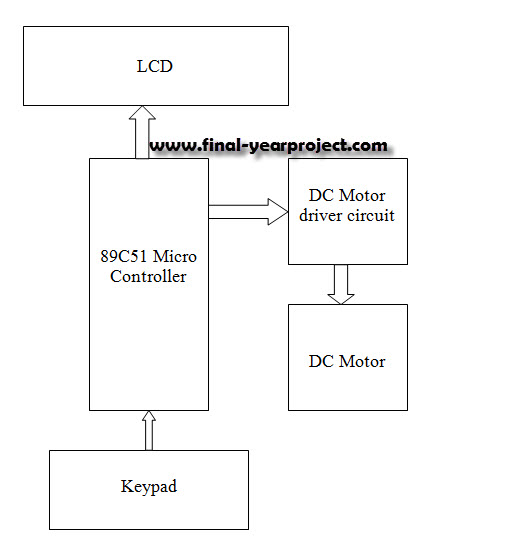
This report details an electronic project focused on the speed control of a DC motor using a microcontroller and PWM (Pulse Width Modulation). The system integrates a microcontroller with an LCD, keypad, and a DC motor driver. The microcontroller...

This smoke detector electronic project is designed using the LM1801 and common electronic components. The smoke detector circuit diagram does not utilize ionization detection, gas sensors, or optocouplers; instead, it employs two photoresistors (LDRs) and an LED. The circuit...
This project operates red, amber, and green LEDs in the correct sequence for a single UK traffic light. The duration of the complete sequence—red, red & amber, green, amber—can be adjusted from approximately 7 seconds to about 2.5 minutes...

The input capacitor is used for low-frequency cut-off, with a standard value of 0.1 µF, resulting in a cut-off frequency of approximately 16 Hz. The input capacitor plays a critical role in electronic circuits, particularly in signal processing and audio...
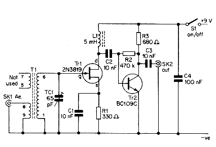
This simple aerial booster circuit design could serve as an alternative or a hobby project for creating an aerial booster device for Citizen Band (CB) radio. The aerial booster circuit is designed to enhance the performance of Citizen Band (CB)...
This circuit was inspired by a friend who wanted a reverb for his portable guitar amplifier. I originally tried using NE5532 low noise op-amps for the buffer stages but they were too noisy for the low level circuits so...