
Traffic Light Project

The circuit utilizes a 555 timer configured in astable mode to generate a continuous square wave signal. This signal acts as a clock input for the 4017 decade counter, ensuring that each output is activated in a sequential manner. The timing of the sequence is controlled by a variable resistor (1M preset), allowing for flexible adjustment of the overall cycle duration.
In the design, the red LED is powered directly from the Q10 output of the 4017, which remains high for the initial five counts (Q0 to Q4). This approach effectively reduces component count and complexity, as it eliminates the need for additional diodes that would otherwise be required to control the red LED. The amber and green LEDs are driven by specific outputs of the counter, with diodes ensuring that each LED operates correctly without interference from other outputs.
The circuit's operation can be summarized as follows: upon powering the circuit, the 555 timer begins oscillating, producing clock pulses that increment the counter. The first five pulses activate the red LED, followed by a transition to the amber LED with the next output. The green LED is activated subsequently, and finally, the amber LED lights up again before the cycle restarts. This sequence mimics a standard traffic light operation, providing a clear visual indication of traffic signals.
Overall, this circuit design is efficient, utilizing minimal components while maintaining functionality and adaptability for various timing requirements. The choice of LEDs, particularly the option to use a yellow LED instead of amber, enhances visibility and ensures adherence to traffic signal standards.This project operates red, amber and green LEDs in the correct sequence for a single UK traffic light. The time taken for the complete red - red & amber - green - amber sequence can be varied from about 7s to about 2 ½ minutes by adjusting the 1M preset.
Some amber LEDs emit light that is almost red so you may prefer to use a yellow LED. The 555 a stable circuit provides clock pulses for the 4017 counter which has ten outputs (Q0 to Q9). Each output becomes high in turn as the clock pulses are received. Appropriate outputs are combined with diodes to supply the amber and green LEDs. The red LED is connected to the G·10 output which is high for the first 5 counts (Q0-Q4 high), this saves using 5 diodes for red and simplifies the circuit. 🔗 External reference
Related Circuits
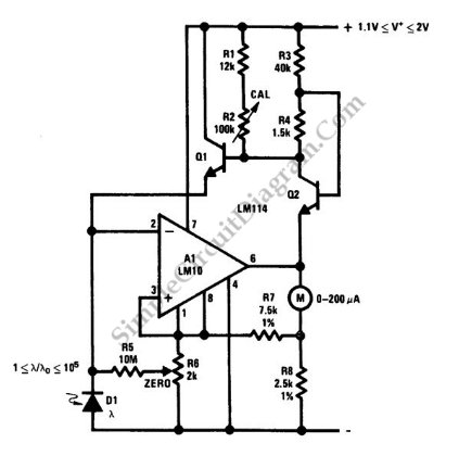
This is a portable light-level meter circuit with a five-decade dynamic range. It utilizes a single-cell battery as the power supply. To calibrate this circuit, The portable light-level meter circuit is designed to measure light intensity across a wide...
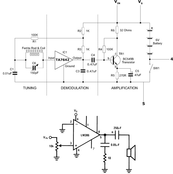
This functioning radio was built for an electronics module. The specified design was modified to include batteries, a switch, and a speaker instead of headphones. An additional amplifier circuit was required to power the speaker driver. Although not necessary,...
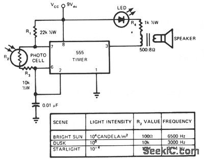
This circuit's frequency of oscillation increases directly with light intensity. The greater the light intensity, the higher the frequency of the oscillator. The 555 timer operates in astable oscillator mode, where frequency and duty cycle are controlled by two...
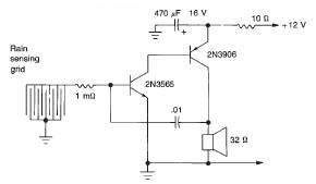
This rain detector electronic circuit project is a simple alarm circuit that activates an audio warning when liquid is detected on the sense pad. The circuit diagram is based on two transistors. When the sense pad conducts, transistors Tr1...
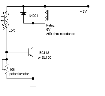
The following circuit illustrates a Light Barrier Sensor Detector Circuit Diagram. Features include a single transistor, an adjustable potentiometer, and a 6V power supply. The Light Barrier Sensor Detector Circuit is designed to detect the presence of an object by...
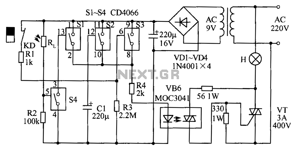
The circuit diagram illustrates a group of four analog electronic circuit switches (S1 to S4). Switches S1, S2, and S3 are utilized in a parallel delay circuit. When the power is activated, resistor R4 drives the triac VT, which...