
brain wave machine

The design of the brain-wave goggles integrates both hardware and software components to facilitate an engaging user experience. The LEDs serve as the primary visual stimuli, illuminating in patterns that can be programmed to synchronize with audio stimuli, enhancing the overall effectiveness of the brain-wave entrainment process. The choice of safety glasses as the base for the goggles provides a durable and comfortable fit, ensuring that the user can wear them for extended periods without discomfort.
The arrangement of the LEDs in a diamond pattern on each lens is critical for achieving a balanced visual effect, allowing for optimal light exposure to the user's eyes. This configuration not only enhances the aesthetic appeal of the goggles but also maximizes the effectiveness of the light stimulation. The use of the parallel port for control allows for real-time adjustments to the LED flash rates, providing flexibility in experimentation with different stimulation patterns.
In terms of assembly, attention to detail is essential. Ensuring that the cathode and anode leads are correctly connected is vital for the functionality of the circuit. The use of strain relief mechanisms will help maintain the integrity of the connections, reducing the risk of disconnections during use. The entire assembly process should be conducted with care to ensure safety and reliability, particularly when incorporating electronic components with wearable devices.
Overall, this brain-wave goggles project exemplifies a practical application of electronics in personal wellness, combining visual and auditory stimulation to potentially enhance cognitive function and relaxation. Properly executed, this design can serve as a valuable tool for individuals interested in exploring brainwave entrainment techniques.With simplicity being the goal, brain-wave goggles can be constructed from suitable eyewear, such as safety glasses, and an array of LED`s (Light Emitting Diodes). I`m using the PC`s parallel port to control the flashrate of the LED`s. Audio stimulation can be provided by a stereo and headphones or the PC`s soundcard. I`m using 8 LED`s, one per parallel port data out line. This provides an easy way to control each individual LED allowing for some variations in pattern and intensity. Each lense on the goggles will hold four LED`s in a diamond pattern. The LED`s are powered by the parallel port and controlled via softw1are. Glue the LED`s into the holes. Be sure there is room betw1een the LED`s and your face when you are wearing the goggles. Actually, the LED`s fit tightly in 3/16" holes and I didn`t need to use glue. Wire all of the LED`s cathode leads together and connect (with a long wire) to a ground pin on the parallel port connector.
Pins 18-25 are all ground so pick any one of those. Note: the flat side of the LED is the cathode lead. Connect the LED`s anode leads to the parallel port connector. Follow the circuit diagram above which outlines which parallel port pin to connect each LED to. Use long wires, you are going to want to be lying down when you use the goggles. (If you are using a printer cable you can use a battery and a LED to figure out which pin each wire is attached to. ) If your parallel port wires aren`t already in a bundle tie them together with wire-ties so they don`t get tangled.
You will also want to provide strain-relief by attaching the wire bundle to the goggles so it doesn`t get pulled off. 🔗 External reference
Related Circuits
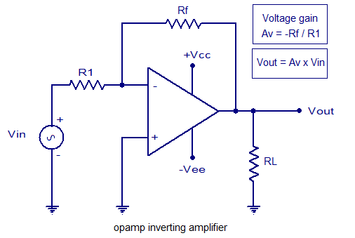
An inverting amplifier utilizing an operational amplifier (op-amp). This includes equations for voltage gain and output voltage, as well as input and output waveforms, and a practical inverting amplifier circuit using the 741 IC. An inverting amplifier is a fundamental...
This sine wave generator is adjustable between 15 Hz and 150 kHz. The circuit is essentially a Wien-bridge oscillator, featuring multiple capacitor selections. The sine wave generator operates on the principle of the Wien-bridge oscillator, which is known for producing...
The circuit presented illustrates that despite the availability of various new components and technologies, it remains feasible to design useful and interesting circuits. The circuit utilizes two well-established transistors, the BF256C and the BF494. Along with the necessary resistors...
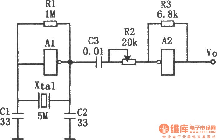
The sine wave generator composed of an inverter is illustrated in the chart. This circuit can produce a high-stability sine wave at frequencies exceeding a few megahertz. In the diagram, A1 and the crystal oscillator create an oscillating circuit,...
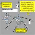
This Antenna is most widely used all over the world. For example, when you see a police car it has a transmitter with Ground Pole Antenna. The body of the car serves as ground. It accepts load from a...
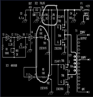
The circuit includes 10K resistors at the bases of the transistors and 1K resistors at the collectors. It is essential to retain these components when relocating the transistors, as omitting the 10K resistors could result in transistor failure, and...