
brake sensor

To troubleshoot, disconnect the connector and measure the resistance across the two pins on the side with the shorted wires (previously attached to the pads). The resistance should be less than 1 ohm; if it exceeds this value, the connection must be remade. Clean the pin and socket connections on both sides of the connector, as this is often the source of the issue. Use contact cleaner to ensure good connectivity. Once reconnected, start the vehicle with the brake pedal depressed, shift into gear, and check if the warning light remains illuminated (it should only activate when the vehicle is in gear). If the light turns off, the bad connection has been identified. If it does not, further resistance readings should be taken as previously described. Ensure to clean the sensor connector contacts on both the male and female sides. Resistance readings across the two contacts should again be less than 1 ohm; if not, the connections need to be remade.
To continue troubleshooting, locate the three-pin connectors T3g and T3h in the engine compartment, typically positioned at the lower front, forward of the wheels on either side. The belly pan may need to be removed for access. Perform a continuity check from the brake pad side of pin 1 on T3g to the brake pad side of T3h pin 1. Disconnect these connectors and use a multimeter set to the resistance range; continuity should read 1 ohm or less. Measure continuity across each brake pad wear indicator as illustrated. One indicator will likely show continuity while the other will be open-circuited. Identify the open-circuited indicator and repair it by shorting the brake pad wear sensor wires. This issue often arises when aftermarket pads are used that lack the necessary sensors.The brake pad warning light is designed to come on when the front brakes wear down to about 25% left on the pads. It is triggered by an insert in the pads that has two wires attached. The wiring and pad is part of a ground loop that starts at the instrument cluster, goes through both brake pads and to ground.
Once this path is broken, the brake pa d warning light comes on. However, many aftermarket brake pad sets do not have the sensors installed. Therefore, the old sensors must be cut off the old pads, the wire insulation stripped, the wires twisted together, wrap them in electrical tape, fold them over and tie wrap the whole thing up. Then plug it into the car side harness. This maintains continuity in the circuit, which will prevent the brake pad wear sensor light from coming on.
Brake sensor wiring cut off old pad, shorted out, taped up and tie wrapped in place. This will maintain circuit continuity so the brake pad warning light won`t come on. In the case that this was done, but the light still comes on, it needs to be troubleshot. The following outlines how to troubleshoot the bad connection. Remember, the circuit should be a short circuit. The brake pad warning light comes on when the circuit opens. The brake pad warning light circuit is a ground path loop. When this ground path is interrupted (open circuited, like turning a light switch off), the brake pad warning light (K32 in image) comes on. The brake pad wear circuit starts from the back of the instrument cluster (pin 25 on red 26 pin connector), through the firewall somewhere, to T3g, pin 1 (3 pin connector back left of engine compartment) to N13, which is the brake pad wear indicator, left.
It then goes back to T3g, pin 2 and over to T3h, pin 2 to N12, the right brake pad wear indicator. Then back through T3h, pin 1 which is then connected to chassis ground at point 83. 83 is ground connection 1, in right front wiring harness. Follow that path, it goes from the sensing circuit which is at 12 VDC to ground at point 83 which is chassis ground. When this circuit is interrupted, the light comes on. Easy Yes, it really is. Unplug the connector and on the side with the shorted wires (that use to be attached to the pads) take a resistance reading across the two pins.
This should be less than 1 ohm resistance. If greater than 1 ohm, remove the tape and remake the connection. Ensure it is less than 1 ohm. Clean the pin and socket connections on each side of the connector. This is most likely where your problem is. Use contact cleaner from Radio Shack with a small brush. Make up the connection, start the car with your foot on the brake, then put it in gear and check for the light (will only light up with the car in gear). If it went away, you`ve found your bad connection. If not, take resistance readings to ground as outlined below. Ensure you clean the contacts of the sensor connector on both male and female side. This is most likely the problem. Follow directions above. Resistance readings across the two shown contacts should be less than 1 ohm. If not, remake connections. So how to troubleshoot Pretty easy. Find three pin connectors T3g and T3h in the engine compartment. I believe this connector is down at the bottom front of engine compartment, forward of the wheels on each side.
The belly pan would have to be removed first. Perform a continuity check from the brake pad side of pin 1 on T3g to the brake pad side of T3h pin 1. You disconnect these connectors, hook up a multimeter on the resistance range, and you should have 1 ohm or less for continuity.
Measure the continuity across each of the brake pad wear indicators as shown in the image. One will most likely be shorted (continuity) and the other will be open circuited. Find the one that is open circuited and repair as required by shorting the brake pad wear sensor wires. You probably put on aftermarket pads that didn`t have them and now the old ones nee 🔗 External reference
Related Circuits
This light sensor switch circuit enables the automatic activation of a lamp when ambient light levels decrease, such as during nightfall. The duration for which the lamp remains on can be adjusted using potentiometer P1, with a range of...
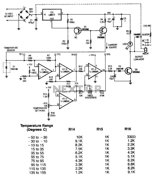
The LM35 temperature sensor outputs 10 mV/C for each degree Celsius above 0°C. At 20°C, the output voltage is calculated as 20 × 10 = 200 mV. The circuit consumes minimal power. Additionally, the load resistance should not be...
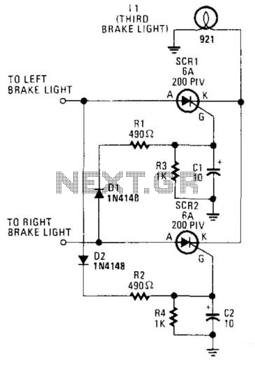
The circuit is designed to illuminate the third brake light (via SCR1 and SCR2) only when both the left and right brake lights are activated. The circuit operates on 12-V negative-ground systems. When the brake pedal is depressed, 12...

Shadow sensors are commonly utilized to detect the movement of an individual in a confined space. Numerous previously published circuits exhibit a significant limitation, as they only... Shadow sensors operate by detecting changes in light intensity caused by the movement...
One basic method for distance measurement involves using an ultrasonic transducer. The principle is to send a burst of ultrasonic waves towards an object, which reflects the waves back to the ultrasonic receiver. By measuring the time delay between...
This is an ultrasonic motion detector circuit with high movement sensitivity. It can detect even minor air movements, such as hot air rising or wind blowing, when the trimpot is adjusted to a sensitive position. The transmitter emits a...