breadboard How does current flow through this Arduino circuit
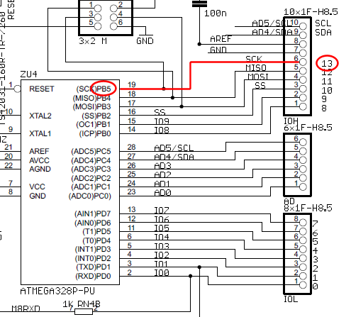
The wire connected to the 5V pin is linked to the positive pins of the breadboard, which are not connected to any other components. There are no additional connections on the positive column. While this may seem like a basic question, the lack of specific terminology has made it challenging to find a clear explanation of current flow in an Arduino.
In an Arduino circuit, the 5V pin serves as a power output, providing a stable voltage supply to various components connected to the breadboard. The positive rail of the breadboard is typically used to distribute this voltage to multiple components, allowing for a common power source. When a wire is connected from the 5V pin to the positive rail, it establishes a pathway for current to flow from the Arduino to any devices or components that require power.
For effective current flow, it is essential to ensure that the positive rail is connected to devices such as sensors, LEDs, or microcontrollers that can utilize the supplied voltage. If the positive rail is left unconnected, as indicated, there will be no current flow, rendering any connected components non-functional.
In addition to the 5V pin, the Arduino also features ground (GND) pins, which should be connected to the negative rail of the breadboard. This establishes a complete circuit, allowing current to flow from the 5V pin, through the connected components, and back to the Arduino via the ground connection. Proper connections are crucial for the functioning of any electronic circuit, and understanding the relationship between the voltage supply and the components is fundamental to circuit design and implementation.
For those unfamiliar with electronic terminology, it may be beneficial to explore basic concepts such as voltage, current, and resistance, as well as the function of breadboards in prototyping circuits. This foundational knowledge can aid in effectively utilizing Arduino and similar platforms for various electronic projects.It seems to me like the wire connected to the 5v pin is connected to the + pins of the breadboard. which are connected to nothing. There`s nothing else on the + column. I know this is a basic "google it" question, but probably due to the fact that I don`t have the vocabulary to do so I`ve not been able to find a description of current flow in an Arduino. 🔗 External reference
