
Interfacing hex keypad to 8051. Circuit diagram and assembly program. Simple circuit using minimum components

The interfacing of a hex keypad with the AT89S51 microcontroller involves several key components and considerations for effective operation. The hex keypad typically consists of 16 keys arranged in a matrix format, allowing the user to input hexadecimal values (0-9 and A-F). The microcontroller serves as the brain of the system, processing the input from the keypad and executing corresponding commands.
In the circuit diagram, the hex keypad is connected to the microcontroller's I/O ports. Each row and column of the keypad is wired to specific pins on the AT89S51, enabling the microcontroller to detect which key is pressed through a scanning technique. When a key is pressed, the microcontroller reads the logic level changes on the designated pins, determining the key’s position based on the row and column activated.
The assembly language program is designed to facilitate communication between the microcontroller and the hex keypad. It typically includes routines for initializing the keypad, scanning for key presses, and debouncing the input to ensure that multiple signals are not erroneously detected from a single key press. The program may also include functionality to display the pressed key on an LCD or send the data to another device for further processing.
Testing of the system is crucial to ensure reliability and accuracy. The provided testing video demonstrates the functionality of the circuit, showcasing how key presses are registered and processed by the microcontroller. This comprehensive setup allows users to effectively interface with the hex keypad, enabling a wide range of applications such as input devices for embedded systems, user interfaces for various electronic projects, and more.Interfacing hex keypad to 8051. AT89S51 is the microcontroller. Circuit diagram and assembly language program. Testing video also provided.. 🔗 External reference
Related Circuits
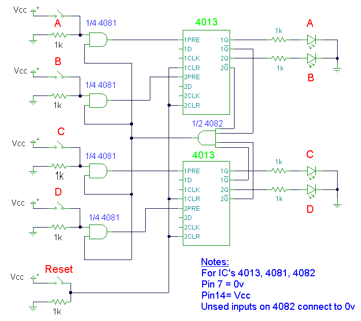
This design utilizes four integrated circuits (ICs) and features four input circuits with four independent outputs, along with a single master reset switch. The outputs are configured with light-emitting diodes (LEDs), which can be modified to control lamps or...
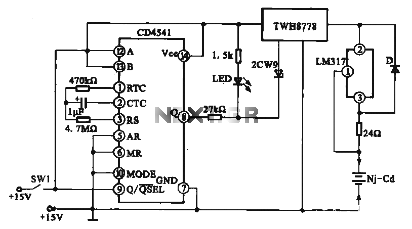
A constant current charging circuit with a long delay is implemented using the CD4541, which constitutes a constant current charging circuit suitable for Ni-Cd batteries. Upon powering on, the CD4541 output at pin high activates the TWH8778 electronic switch,...

This LED flasher circuit is a classic two-transistor flip-flop. It is a popular circuit often built by beginners in electronic circuit design. The schematic diagram of this well-known LED flasher circuit consists of two transistors, two capacitors, four resistors,...
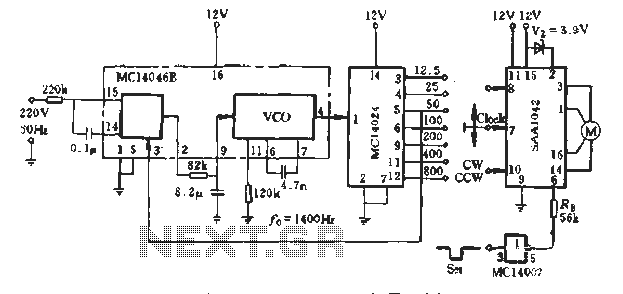
A typical application example is presented, demonstrating the SAA1042 12V stepper motor drive configuration. The phase winding current is set at 200mA. According to RB Figure 5-10, a resistor value of RE = 56kΩ is selected. This resistor is...

The FM radio transmitter is a high-frequency amplifier circuit that utilizes the Mitsubishi frequency set, specifically the M57704H discharge path. It operates within the frequency range of 457-458 MHz and has a transmission power of 5 watts. As illustrated...
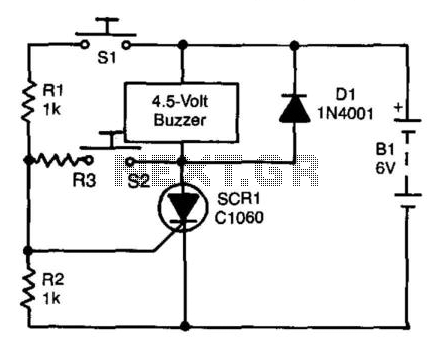
A self-interrupting device connected to a voltage source operates as a switch that continuously opens and closes; thus, the circuit does not latch in the conventional manner, allowing the alarm to function only while switch SI is closed. Due...