
Visual System Simulator circuit

The integration of AWR's Visual System Simulator (VSS) with National Instruments' LabVIEW creates a robust environment for the design and simulation of advanced wireless systems. This co-simulation framework allows for a seamless exchange of data, enhancing the design process for RF circuits and digital signal processing. The VSS acts as the primary simulation engine, generating a variety of signals that can be processed within LabVIEW's graphical programming environment. The introduction of a dedicated LabVIEW block within VSS serves as a crucial interface, enabling real-time data transfer and synchronization between the two platforms.
In practical applications, designers can leverage this integration to create complex system diagrams that incorporate both VSS and LabVIEW functionalities. For instance, a designer may set up a system where multiple signal sources are defined in VSS, simulating various conditions and scenarios. These signals can be routed to the LabVIEW block, where advanced processing, such as filtering and modulation, can be performed using LabVIEW's extensive library of virtual instruments. The results from LabVIEW can then be fed back into VSS, allowing for iterative testing and refinement of the design.
The versatility of this co-simulation environment is further exemplified by its support for various communication standards. Designers can utilize predefined toolkits and functions to ensure compliance with industry standards such as LTE or WiMAX, streamlining the development process. The ability to integrate custom LabVIEW add-ons also enhances the system's capabilities, allowing for tailored solutions that meet specific project requirements.
Overall, the collaboration between VSS and LabVIEW represents a significant advancement in the design of wireless communication systems, facilitating a more efficient and effective approach to circuit simulation and analysis.Achieving the highest possible performance from circuits used in third-and fourth-generation wireless systems is driving a tighter integration of previously disparate tools. Certainly, a level of software synergy is essential when designing circuits for use in today`s wireless systems that employ higher-order modulation techniques together with ad
vanced technologies, such as Orthogonal Frequency Division Multiplexing (OFDM), multiple-input multiple-output (MIMO), and digital predistortion (DPD) circuits, to name a few. As this article illustrates, AWR`s Visual System Simulator (VSS) and National Instruments` LabVieW graphical programming environment are now co-simulating to better enable designers to analyze, optimize, and verify complex RF circuits, subsystems and digital signal processing within a unified framework.
Before looking more closely into specific design scenarios, it is important to understand how this new and cohesive VSS/LabVIEW co-simulation environment works. The integration of VSS and LabVIEW is enabled via a new LabVIEW block within VSS. The simulation is driven by VSS and the LabVIEW block provides the interface to LabVIEW, allowing the exchange of data and parameters between the two platforms (Figure 1).
This new block invokes a LabVIEW virtual instrument (VI) which in turn performs digital signal processing functions programmed through palettes provided in the graphical programming environment. This interface provides flexible configuration options with user-defined mapping of VSS nodes and parameters to the VI input and output ports.
Multiple LabVIEW blocks may be placed on a VSS system diagram so that multiple VIs are executed at the same time. This integration offers VSS and LabVIEW users increased capabilities, such as expanded math and baseband libraries.
The link to the extensive library of LabVIEW VIs also enables access to a large collection of functions for RF instrument control and RF measurements as well as frequently used DSP functions and primitives, signal generation and analysis toolkits for standards such as WiMAX, WLAN, GSM/EDGE, WCDMA/HSPA+ and LTE. Additionally, VSS provides a platform that is known for its ease of use, and also includes a large number of standard and custom signal sources, signal processing capabilities, RF and digital hardware component modeling as well as an extensive set of measurements.
This interface further allows the use of LabVIEW add-ons and toolkits, which provide standard signal sources and measurements; signal processing, analysis and connectivity; integration with development hardware; and many other capabilities. Taking a closer look as to how designers may utilize this new co-simulation environment, the following scenarios are presented: VSS can generate signals required for the design and simulation of modern communication systems.
Real, complex, and digital signal sources can be combined to provide real-world emulation of signals for a wide range of applications. Figure 2 shows a VSS system diagram with several of these signals feeding a LabVIEW block (red circle in Figure 2) and outputs being measured with test points (blue box inset into Figure 2).
The LabVIEW block ties directly to a VI in LabVIEW. The link between VSS and LabVIEW is managed exclusively by this block. During VSS simulation, the time-domain data is fed into the LabVIEW data flow and the resulting VI ouput is resynchronized in time with the VSS simulation. Referring to Figure 2, the integer data in VSS goes to LabVIEW and its amplitude is calculated with a summing function and returned to VSS.
The resulting output (Figure 3) - relative to the input - is scaled in amplitude according to the LabVIEW processing block. The real and complex signals have a similar operation. LabVIEW VIs can also be used from within the VSS environment. Consider a simple VI that takes two input signals, adds them together, and scales the result 🔗 External reference
Related Circuits
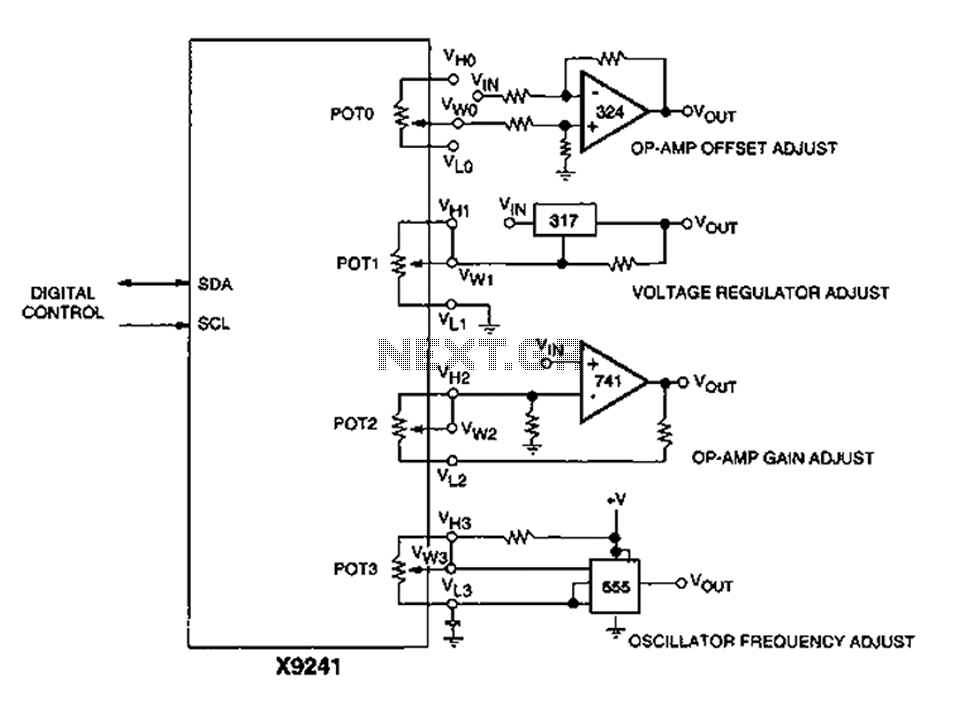
A XICOR X9241 POT IC module can be utilized to modify the four digital analog circuits, as depicted in the schematic. The XICOR X9241 is a digital potentiometer integrated circuit designed for precise adjustment of analog signal levels in various...
This circuit is designed to detect whether the load of a battery charger or plug-in adapter is properly connected. The load may consist of a set of batteries needing charging or any other device that operates on low DC...

This is a simple headphone amplifier circuit designed to drive headphones when a music player lacks sufficient power. The circuit is straightforward and utilizes only three transistors. The first transistor, Q1 (BC 239), along with its associated components, functions...
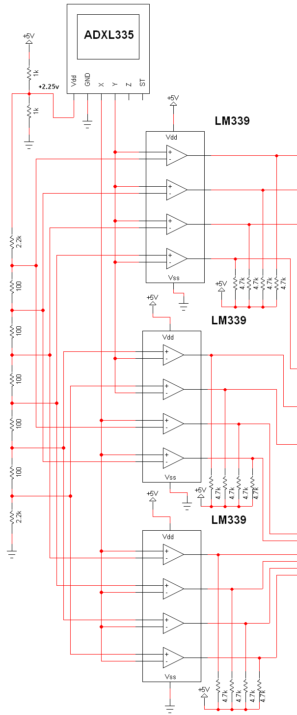
The schematic for this project is extensive, and the complete schematic is displayed below. It is divided into two sections: the analog and digital sections. The schematic illustrates the analog-to-digital conversion circuit, which includes 12 comparators—6 for the X-axis...
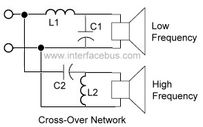
An audio crossover network is utilized within a speaker to separate or filter audio signals of varying frequencies to different speakers inside a speaker cabinet designed for those frequencies. This specific crossover network employs two passive components for each...
The common characteristic of all previous low-power FM transmitters built over the decades is that their operating frequency is determined by an LC resonant circuit. Some of these transmitters exhibited excellent stability, while others did not; however, there has...