
Bridge motor drive circuit

The bridge motor drive circuit is designed to control the direction and speed of a DC motor using a H-bridge configuration. The circuit consists of four transistors arranged in a bridge formation, allowing for efficient control of the motor's operation. The transistors are typically N-channel MOSFETs or bipolar junction transistors (BJTs) capable of handling the required current and voltage levels for the motor.
The four terminals A, B, C, and D serve as inputs to the control circuit. When specific combinations of these inputs are activated, they switch the transistors on and off in a manner that determines the motor's direction. For example, activating terminals A and B may cause the motor to rotate in one direction, while activating terminals C and D would reverse the rotation. This configuration enables bidirectional control of the motor, making it suitable for applications requiring precise movement.
The control mode can be set to manual, allowing an operator to directly control the motor's direction using switches or buttons connected to the terminals. Alternatively, an automatic control mode can be implemented, where a microcontroller or other automation system manages the inputs based on pre-defined parameters or sensor feedback. This flexibility in control methods enhances the circuit's versatility for various applications, from robotics to conveyor systems.
Additionally, protective components such as diodes may be included to prevent back EMF generated by the motor from damaging the transistors. Heat sinks may also be necessary to dissipate heat generated during operation, ensuring reliable performance and longevity of the circuit. Overall, the bridge motor drive circuit provides an effective solution for controlling motor functions in a wide range of electronic and electromechanical systems. Bridge motor drive circuit Bridge motor drive circuit is shown, the driving stage of the circuit is 4 transistors. The control circuit is provided with four ends, through to A, B, C, D can control the forward or reverse rotation control. Control mode can be used manually or automatically.
Related Circuits
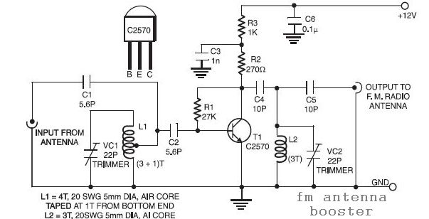
The input coil L1 is composed of four turns of 20 SWG enamelled copper wire, wound slightly spaced over a 5mm diameter former. It is tapped at the first turn from the ground lead side. Coil L2 is similar...
The T-40-16 and 555 ultrasonic transmitter circuit configuration consists of an ultrasonic transmitter T-40-16 and a 555 timer circuit. By adjusting the potentiometer RP, the oscillation frequency of the circuit can be changed. The output pulse frequency from the...
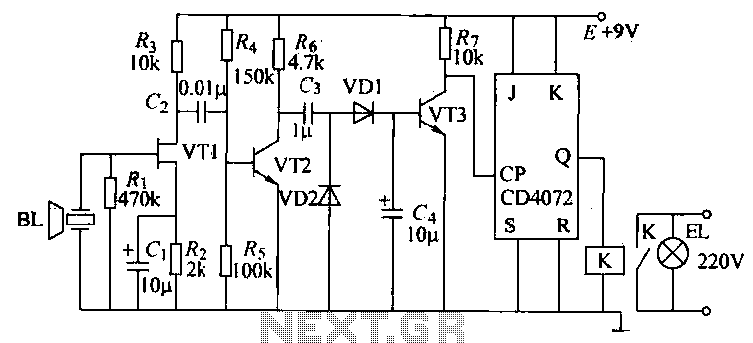
The purpose of this circuit is to power a lamp or other appliance for a specified duration (30 minutes in this case) and then automatically turn it off. This functionality is particularly useful for reading in bed at night,...
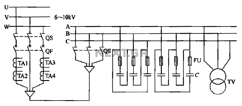
The compensation system is designed to focus on a high-pressure, high-voltage capacitor bank installed in the substation 6-10 kV bus. Compensation can only be implemented in this manner for the 6-10 kV bus before the reactive power on the...
The circuit features four pins labeled "Controller pin 1," "Controller pin 2," "Controller pin 3," and "Controller pin 4," which are responsible for controlling the motion and direction of the stepper motor based on the step sequence programmed into...
This unit captures the ATV signal by sampling the transmission line with minimal insertion loss. It features two N connectors for input and output connections, and a BNC connector is utilized for the video output. The detected output is...