
Brief introduction of circuit diagram of the inverter and principle

The inverter circuit described operates on the principle of converting 12V DC to 220V AC, which is achieved through a series of operational amplifiers and switching components. The primary components include BG1, BG2, BG3, BG5, and gas switching tubes. The circuit begins with a voltage doubling stage, where an operational amplifier, such as ICL7660 or MAX1044, generates a 50 Hz sine wave as a reference signal. This reference signal is critical for the operation of the inverter, as it provides the necessary timing for the switching elements.
The inverter employs a multivibrator configuration using BG2 and BG3, which generates a square wave output. This output drives BG1, which in turn controls the operation of the gas switching tubes (BG6 and BG7). The switching frequency is determined by the feedback from the operational amplifiers, specifically operational amplifiers 3 and 4, which function as hysteresis comparators. These comparators ensure that the switching action of the gas tubes occurs alternately, allowing for the conversion of DC to AC.
The output stage of the inverter utilizes a transformer capable of stepping up the voltage from 12V to 220V AC. The transformer is designed to handle the output waveform, which is primarily rectangular due to the nature of the switching action. This design choice balances the need for simplicity in construction and the requirement for a compact form factor.
In practical applications, the inverter circuit can be used to power various household devices during a power outage, including lighting systems and electronic appliances. The choice of components and the overall design emphasize reliability, ease of assembly, and effective performance in converting DC to AC power. The inverter's ability to operate efficiently with renewable energy sources further enhances its appeal in modern applications, where sustainability and energy independence are increasingly prioritized.The inverter is kinds of direct currents can battery, storage battery Change into alternating current generally 220 volts of 50HZ sine waves or rectangular waves Device. Our common emergency power supply, 220V exchange to generally all invert the direct current bottle. Come briefly and say, the inverter is that one kind turns direct current into e xchanging the electric device. No matter in the remote mountain village, either open-air need or the black out meets an urgent need, the inverter is a very good choice. The more common one is UPS power which will be used in computer lab, in the unexpected black out, UPS can invert and exchange and is used as computer the direct current of Reed of storage battery, thus prevent the data caused by unexpected deenergization from losing the question.
Can the at a stretch offer the power, have sure safe reliability, stability. The inverter can also be with the corollary use of the generator, Yes the economy of fuel, reduction noise effectively, in the fields of wind energy, solar energy, the inverter is more essential. Small-scale inverter usable car, steamer, portable power supply equipment offer the AC supply outdoors.
This text will introduce two kinds of simpler inverter schematic diagrams. This kind of design, the material is apt to fetch, output power 150W, this circuit designs frequency as about 300HZ, the purpose is narrowing and reversing the volume, weight, output waveform rectangular wave of the voltage transformer. The family lights when this inverter can be used in the black out, the daylight lamp of the electronic ballast, other respects such as the household electrical appliance of switching power supply.
This inverter is comparatively apt to make, can go against 12V direct-flow mains voltage to turn into the voltage of 220V city power, the multivibrator of the circuit composed of BG2 and BG3 is pushed, and then drive through BG1 and BG2, to control BG6 and BG7 work. Resonator supply power by BG5 and the intersection of DW and stabilized voltage supply of group, so can make, output frequency comparison to be steady among them.
While producing, voltage transformer available to have daily pairs of city power voltage transformer that 12V exports. Depending upon need, are chosen the appropriate 12V battery capacity. 12V is battery-driven that this circuit takes. Supply power for the Operational Amplifier with the module voltage doubling of a voltage doubling first.
Can choose ICL7660 or MAX1044. The operational amplifier 1 produced 50Hz sine wave as the reference signal. The operational amplifier 2 is regarded as the inverter. The operational amplifier 3 and operational amplifier 4 are regarded as the hysteresis comparator. In fact the operational amplifier 3 and what the gas switching tube 1 formed are the switching power supply of proportions. The operational amplifier 4, with the gas switching tube 2 too. Its switching frequency is unstable. When an outcoming signal of operational amplifier is a normal phase, operational amplifier 3 and gas switching tube work.
2 ones that exported of operational amplifier are to shoulder the looks at this moment. The intersection of operational amplifier and 4 electric potential 0 of positive input terminal at this moment Always higher than the electric potential of the negative input terminal, so the operational amplifier 4 is exported permanently as 1, the gas switching tube is shut off. Opposite in order to shoulder at the time of the looks in the one output of operational amplifier. This realization is two gas switching tube alternation. When the actuating signal ratio testing signal of the basic reference, it is a minification value of Senior One of signal of the actuating signal ratio positive input terminal of the negative input terminal of operational amplifier 3 or 4 too, the comparator exports 0, the gas switching tube is turned on, thereupon the testing signal is impro
🔗 External reference
Related Circuits
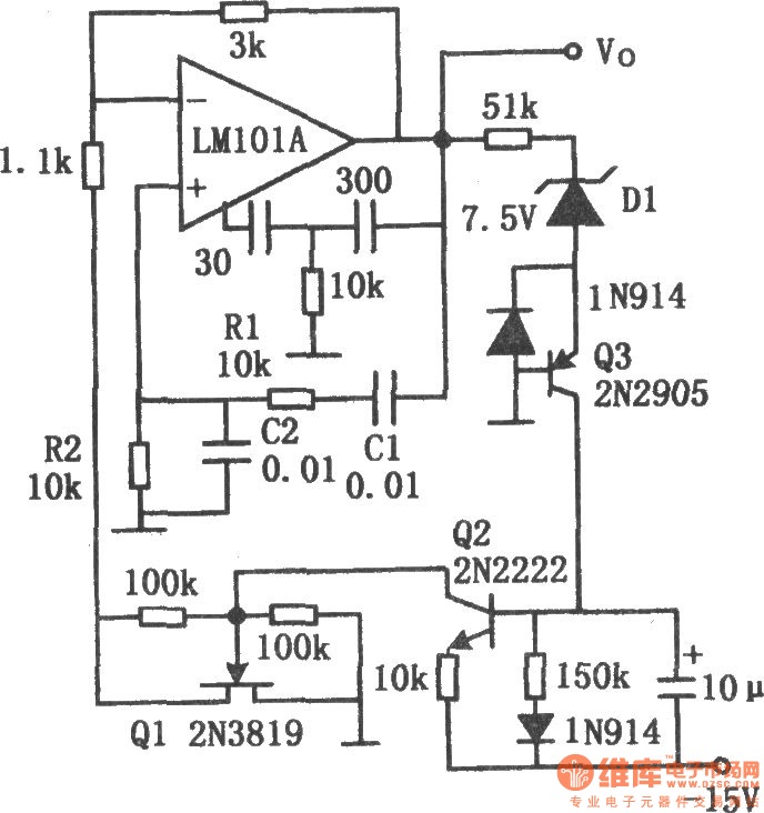
The chart illustrates the Wien bridge sine wave oscillator circuit. The amount of negative feedback in the circuit is determined by the internal resistance of the FET. When the peak output voltage of the oscillator reaches the regulated voltage...
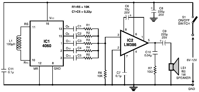
The circuit is built around the popular CMOS oscillator-divider IC 4060 and a small audio amplifier LM386. The IC 4060 functions as a multitone generator. A 100 H inductor is used at the input of the IC 4060, allowing...
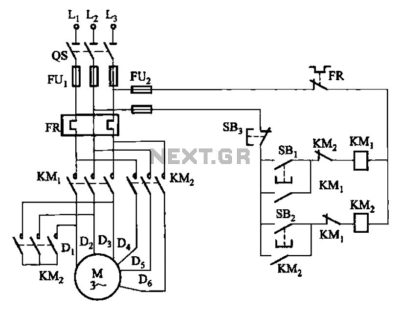
The circuit illustrated in Figure 3-97 features two contacts and is designed specifically for a 2kW dual-speed motor. In this configuration, SB1 is utilized for low-speed operation, while SB2 serves as the high-speed run button. The circuit operates by allowing...
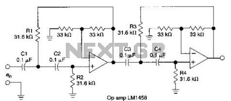
This circuit, which utilizes an LM1458 or a similar operational amplifier, functions as a fourth-order high-pass filter with a roll-off rate of 24 dB per octave. The resistor values Rx/R2 and RJRV can be adjusted to accommodate different cutoff...
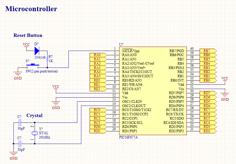
To operate a microcontroller, basic components are required to support its functionality, which is referred to as a basic circuit. The components needed are common and readily available at any electronics store. This document presents the schematic of a...
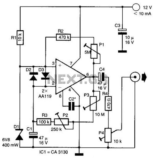
This circuit generates noise pulses suitable for test purposes. A Zener diode serves as the noise source. IC1 functions as a relaxation oscillator. P1 determines the noise bandwidth, while P2 and P3 control the noise amplification. The current consumption...