
Room Monitor Circuit

The circuit operates by employing a transistor-based buffer (Q1) to ensure that the right-channel audio output maintains its integrity and balance, preventing signal degradation. The VOX (Voice Operated Switch) circuit, formed by transistors Q2 and Q3, is responsible for detecting the audio signal from the microphone. When the audio signal exceeds a predetermined threshold, the VOX circuit activates, resulting in a high output signal. This action triggers the multiplexer within integrated circuit IC1 to select the high-gain output from the left-channel, effectively routing it to the next stage of the circuit, which is a buffer stage designed to further amplify the signal without introducing noise or distortion.
The AC coupling capacitor (C3) plays a critical role in the circuit by blocking any DC component of the signal, allowing only the AC signal to pass through to the RF mixer stage. This is essential for ensuring that the RF mixer operates efficiently, as it mixes the incoming audio signal with a local oscillator signal to generate intermediate frequency (IF) signals suitable for further amplification.
The RF amplifier stage is tuned using the components C2 (a capacitor) and L2 (an inductor), which together form a resonant circuit. This tuning allows the RF amplifier to selectively amplify signals at a specific frequency while attenuating others, enhancing the overall performance of the circuit. The careful selection of these components is crucial for optimizing the frequency response and ensuring that the desired audio signals are processed effectively. Overall, this circuit design showcases a well-integrated approach to audio signal processing, combining buffering, signal detection, mixing, and amplification in a coherent manner. The circuit uses Ql to buffer the right-channel balance output while Q2 and Q3 form a VOX circuit. When the signal level from the microphone goes high, the output of the VOX also goes high and the multiplexer inside IC1 switches the high-gain left-channel output through to a following buffer stage. This signal is then ac-coupled via C3 into an RF mixer stage and thence to an RF amplifier, which is tuned by C2 and L2.
Related Circuits
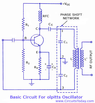
Colpitts oscillator circuit diagram and theory. Colpitts oscillator frequency equation. Colpitts oscillator using transistor. Colpitts oscillator using op-amp. The Colpitts oscillator is a type of electronic oscillator that generates sine waves and is widely used in various applications such as...
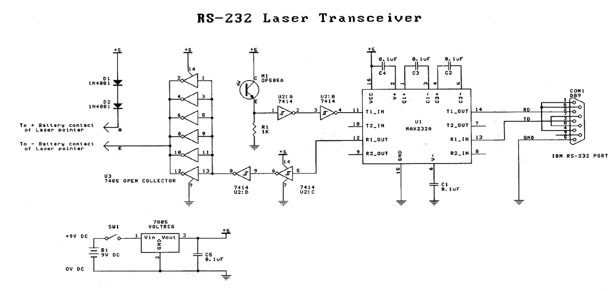
Laser based projects used to be expensive, until the development of solid state lasers. This project is designed for the entry level laser experimenter. The circuit allows any two computers with serial (RS-232) communication capability to communicate over 200...
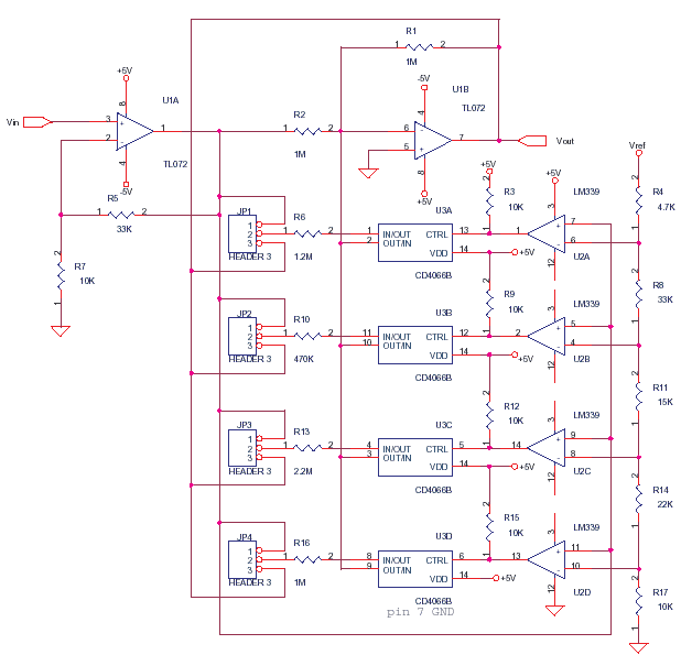
This circuit adjusts the gain of operational amplifier U1B in four distinct steps or segments. It is designed to achieve a linear output from various transducers at levels of 1%. Operational amplifier U1A serves as a buffering amplifier to...
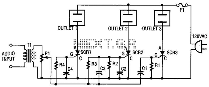
The AC line power is introduced into the circuit through F1, a protective 5-A fuse. One side of the AC line is connected to one side of each AC outlet, while the other side is connected to each silicon-controlled...

This 4-channel commutator utilizes the 2N4091 to achieve a low channel ON resistance (approximately 30 ohms) and minimal OFF current leakage. The DM7800 voltage translator is a monolithic device that provides gate drive voltages ranging from 10V to 20V...
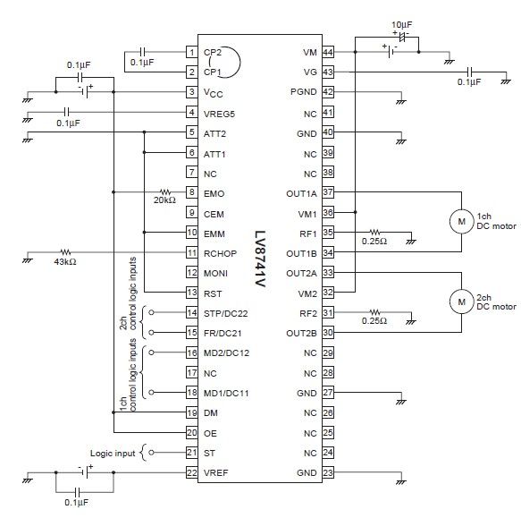
The circuit diagram illustrates an electronic project that requires a few external electronic components. The PWM current-control stepping motor driver IC can provide a maximum output current of up to 1.5 amperes. The configuration settings for the PWM current-control...