
Frequency-Ratio Monitoring Circuit

The circuit operates by utilizing a frequency divider mechanism, which is essential in applications requiring precise frequency control. The two input frequencies, denoted as f1 and f2, are fed into the circuit, where they are processed to yield an output frequency (fout) that is a function of their ratio (fout = k * (f1/f2), where k is a constant that defines the scaling of the output).
The switch, referred to as G1 in the description, is a crucial component that modulates the flow of pulses based on the input frequencies. Each pulse of the bias frequency activates G1 for a specific duration, T, which is determined to be half of the period of the second input frequency (T = 1/(2*f2)). This timing ensures that the circuit allows a defined number of pulses to pass through, specifically fg/f2 pulses, where fg represents the frequency of the bias signal.
The design may incorporate additional components such as resistors and capacitors to filter the signals, ensuring that the output frequency is stable and free from noise. Furthermore, the circuit can be implemented using various technologies, including discrete components or integrated circuits, depending on the application requirements and desired performance characteristics.
In summary, this circuit provides a method for generating an output frequency that is directly related to the ratio of two input frequencies, utilizing a switch mechanism to control pulse transmission, thereby enabling precise frequency modulation in various electronic applications. This circuit produces an output frequency that is linearly proportional to the ratio of two input freque ncies /i//2. Each pulse of the bias fa (or/) will open G1 for a period T= l//2 so that fg/f2 pulses pass to the output.
Related Circuits
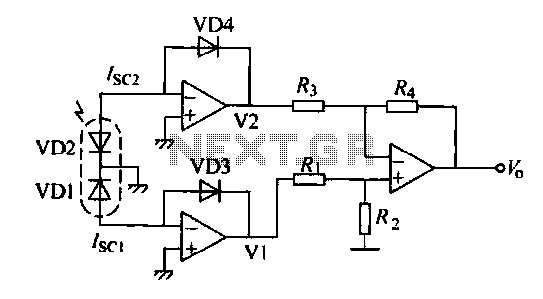
The operation of a semiconductor color sensor can be summarized as follows. The figure illustrates the spectral response curve of two photodiodes that intersect at a specific wavelength. When light of this wavelength is incident on the photodiodes, the...

This design circuit is for audio graphic equalizers, which are commonly found as commercial products, yet published circuits for them are quite rare. The circuit features a simple design that requires an operational amplifier (op-amp) to amplify the input...
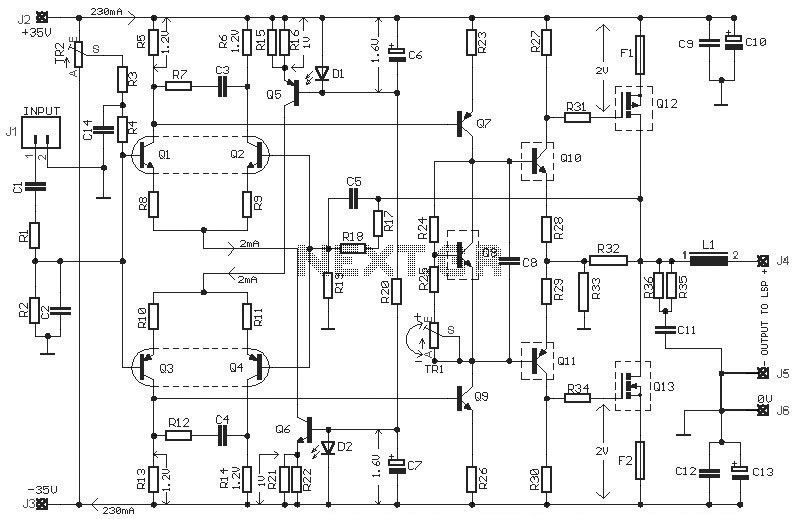
This HEXFET Audio Amplifier 65 Watts circuit diagram includes three circuit images. For a more comprehensive understanding, refer to the original post titled "HEXFET Audio Amp 65 Watts." The post not only provides circuit information but also includes a...
Given the variety of equipment in modern home entertainment systems, the ability to adjust the gain of both audio and video signals has become essential. This particular circuit has proven to be very useful when used alongside the General...
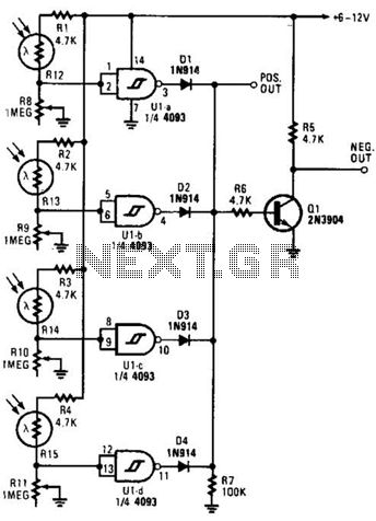
This light-dependent sensor utilizes light-dependent resistors (LDRs) to detect the presence or absence of light. The alarm remains inactive as long as the light source illuminating the LDRs is constant. However, if the light is interrupted, the alarm is activated. The...
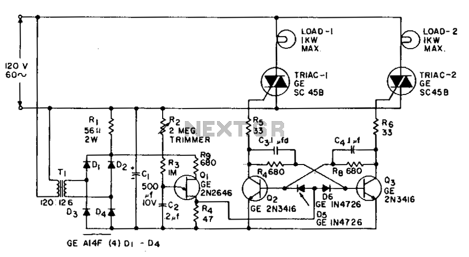
This application involves a static switch circuit where the control logic is implemented using a flip-flop, which is driven by a unijunction transistor. The flashing rate of the circuit can be adjusted, ranging from approximately 0.1 seconds to a...