
Single-phase full-wave rectifier circuit 02 phase

The closed-loop control system described integrates a variety of components to achieve precise motor speed regulation. The stepping motor CNC system's control circuit initiates the process by issuing commands that are detected by the receiver. The phase-sensitive rectifier plays a crucial role in this system by converting the received AC signal into a DC signal, which is essential for accurate control of the motor's operation.
The operational amplifier is pivotal in modulating the conduction angle of the thyristor, which in turn alters the voltage supplied to the three-phase AC induction motor. This alteration changes the strength of the rotating magnetic field, enabling smooth and continuous speed adjustments of the motor. The integration of a tachometer generator for negative feedback is critical for maintaining system stability and enhancing the precision of the motor's performance.
The longitudinal and horizontal AC motors drive the feed screw, facilitating the lathe's operational movements. The design of the phase-sensitive rectifier is particularly noteworthy, as it comprises both a transmitter and a receiver winding that work in tandem to ensure accurate phase detection. The use of a 110V AC supply voltage allows the system to establish a reference angle, which is necessary for determining the angular displacement of the transmitter rotor.
In equilibrium, the system is designed to output zero voltage, indicating that there is no error. However, any deviation from this equilibrium produces a voltage signal that can be processed to correct the error. The single-phase full-wave phase-sensitive rectifier circuit operates effectively by alternating between two groups, allowing for consistent voltage output while utilizing resistive components to maintain balance.
Overall, the system's architecture is designed to provide precise control over the motor's speed, ensuring that the lathe operates efficiently and accurately, with mechanisms in place to adjust for any discrepancies in performance. Closed loop portion is composed of longitudinal and transverse two systems, circuit works briefly as follows: issued by the control circuit of the stepping motor CNC system pav ilion order, the receiver receives the signal, by phase-sensitive rectifier into a DC signal, and then by the operational amplifier, control thyristor conduction angle, the voltage is changed from the three-phase AC induction motor supplier given taro winding, which changed the rotating magnetic field strength, to achieve a stepless adjustment of the motor speed. In order to make the system stable operation, improve the precision and mechanical properties of hardness, it introduced tachometer generator (cs) speed of negative feedback.
Longitudinal (Z) l.lkW and horizontal (X) 550w AC motor drive for the feed screw turning movement, so the lathe work. 2) phase-sensitive rectifier: a transmitter (FZ) winding and a receiver (sz) three-phase windings connected to one correspondence.
110V AC supply voltage transmitter see magnetic windings, that is the initial angle of the receiver at both ends of the stator winding output voltage and phase reflect the transmitter rotor angular displacement hatred that reflect the magnitude and direction of the error angle between the transmitter. At equilibrium, the output voltage is zero, otherwise, an error occurs, a voltage signal output. Figure 2-28 is a single-phase full-wave phase-sensitive rectifier circuit, the two groups work alternately, respectively, in the resistance 5.lk voltage output, RP1 is used to adjust the balance.
The rectified AC into a DC signal, the speed loop RP2 sent to the operational amplifier (ST) llr cream A-side to zoom.
Related Circuits
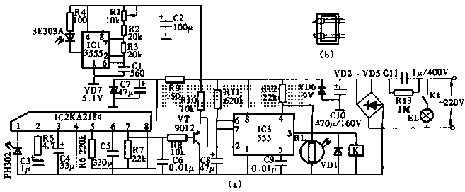
This circuit utilizes the KA2184 infrared receiver ASIC for an infrared remote control dimmer light application, as depicted in the schematic. The infrared signal is generated by a pulse generator using an NE555 timer integrated circuit. The NE555 produces...
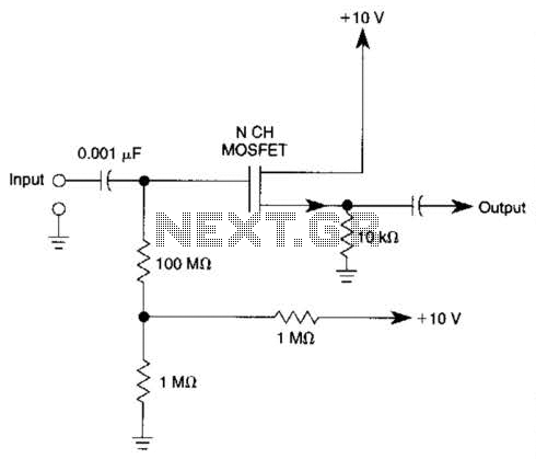
Biasing methods for an N-channel MOSFET to form a unity-gain noninverting amplifier or source-follower. The N-channel MOSFET can be utilized in various configurations, with one common application being the unity-gain noninverting amplifier, also known as a source-follower. In this configuration,...
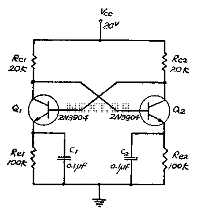
The collector and base-emitter bias of the transistor are directly coupled to each other. Each transmitter circuit controls the capacity conversion function. The emitter generates a triangular wave. The two transistors are not continuously in an active state. Instead,...
This circuit is designed as a warning flasher to alert road users to dangerous situations in low-light conditions. It can also function as a bicycle light, subject to applicable traffic regulations. White LEDs are recommended for use as a...
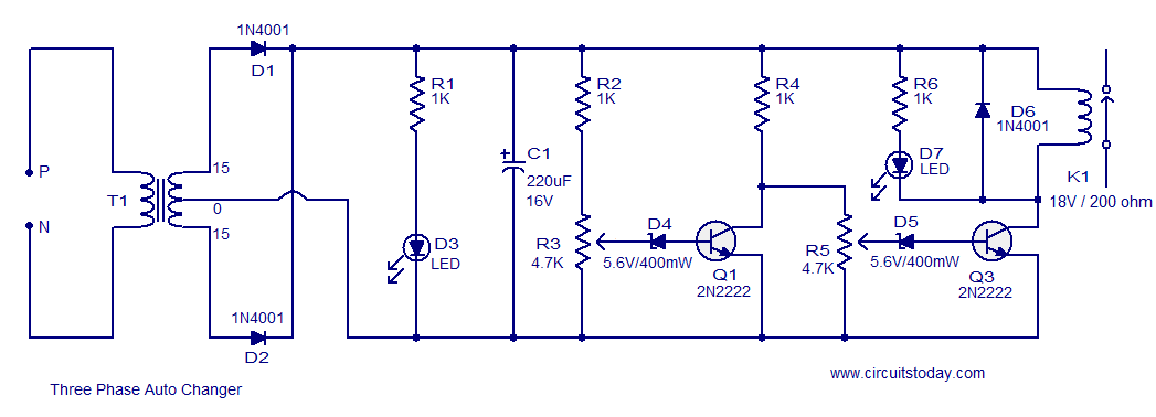
The following circuit illustrates a Three Phase Auto Changer Circuit Diagram. This circuit utilizes the 2N2222 transistor. Features include a transformer. The Three Phase Auto Changer Circuit is designed to automatically switch between different phases in a three-phase power system,...
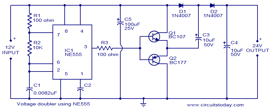
This circuit demonstrates a voltage doubler utilizing the NE555 timer. It is a straightforward project. The NE555 integrated circuit is configured as an astable multivibrator. The NE555 timer is a versatile component commonly used in various electronic applications, including timing,...