
Building the poor-mans mini tesla coil

The circuit in question is a basic transistor circuit that serves as an introductory project for those learning about electronic components and their functions. The primary component, a transistor, acts as a switch or amplifier, depending on the configuration.
To construct the circuit, begin by identifying the type of transistor being used, whether it is a bipolar junction transistor (BJT) or a field-effect transistor (FET). Ensure that the transistor is oriented correctly, with the collector, base, and emitter (for BJT) or source, gate, and drain (for FET) properly aligned with the circuit schematic.
Next, gather the necessary materials, which typically include resistors, capacitors, and a power supply. Resistors may be used to limit the current flowing into the base of the transistor, while capacitors can provide stability and filtering in the circuit. The power supply should match the voltage requirements specified in the schematic to ensure proper operation.
Once all components are assembled, the wiring should follow the schematic closely, ensuring that all connections are secure and correctly positioned. It is advisable to use a breadboard for initial testing to allow for easy modifications if necessary. After wiring, double-check all connections before powering the circuit to prevent damage to components.
Upon successful assembly, the circuit can be tested by applying power and observing the behavior of the transistor. This may involve measuring voltage levels at various points or checking the output signal to confirm that the transistor is functioning as intended.
This simple circuit serves as an excellent foundation for understanding more complex electronic designs and principles.There is not much to this circuit. Above are all the graphics and pictures. After you gather all your materials, take your transistor and wire it up.. 🔗 External reference
Related Circuits
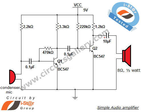
This circuit diagram is a simple and effective design for amplifying weak signals from a capacitive condenser microphone. It is suitable for sound sensing applications and various automatic robotic sensors. While a more complex audio amplifier circuit using the...
The American Electrician describes a glass battery jar measuring six inches by eight inches, wound with 60 to 80 turns of American wire gauge No. 18 B & S magnet wire. Inside this jar is a primary winding consisting...

Using a Thomson TEA2025, this stereo amplifier delivers 1 W per channel into a 4-ohm load with a 9-V supply. The input sensitivity is 25 mV peak-to-peak for full output. It is important to ensure that pins 4, 5,...
A teardown of a BK Precision 4011 5MHz function generator revealed that, like most basic function generators from earlier times, the BK 4011 does not include frequency sweep as a standard option. However, it does feature a VCG (Voltage...
This device is a sensitive instrument that detects frequency changes and the width of an acoustic signal. The brightness of the LED that activates at each moment is proportional to the signal width, while the color corresponds to the...
This is a single transistor pump circuit. It is a straightforward circuit that is quite useful and can serve as a foundational component for designing more complex electronic systems. The single transistor pump circuit utilizes a transistor as the primary...