
Phase-Shift Oscillator For Audio Range

This phase-shift oscillator employs a configuration that generates a sine wave output, making it particularly effective for audio frequency applications. The oscillator's fundamental operation relies on a combination of resistors and capacitors arranged in a feedback loop, which creates the necessary phase shift for sustained oscillation.
In this design, the phase shift is achieved through three identical RC networks, each contributing a 60-degree phase shift, resulting in a total of 180 degrees. The additional 180 degrees required for oscillation is provided by an inverting amplifier, which must have a gain of 29 to ensure that the loop gain is unity at the oscillation frequency.
The resistor R7 plays a critical role in fine-tuning the amplitude of the output sine wave. By adjusting R7, the feedback level can be optimized to prevent distortion while maintaining a stable oscillation. The choice of resistors (R1, R2, R3) and capacitors (C1, C2, C3) is crucial for setting the desired frequency of oscillation. In typical applications, the resistors are selected within a range of 1 kOhm to 100 kOhm, while the capacitors are chosen from 0.1 µF down to 100 pF.
For initial experimentation, setting R to 10 kOhm and C to 0.0068 µF is recommended, which targets an oscillation frequency around 1 kHz. This configuration allows for a balance between stability and performance, making it suitable for various audio applications.
Overall, the phase-shift oscillator is a versatile circuit that can be adapted for different frequency ranges by varying the resistor and capacitor values, providing a practical solution for generating audio signals in electronic applications. This phase-shift oscillator is useful for audio oscillator applications. Adjust R7 for a good sine w ave. An amplifier gain of 29 is required for oscillation. If C=C1 = C2 = C3 and R = Ri = R2 = R3: Typically, R will be 1 to 100 KOhmhm and C will be 0.1 down to 100 pF, in most practical circuits. As a start, choose R = 10 KOhm and C=0.006 8 (for ~ 1-kHz range).
Related Circuits
This circuit is designed for low-power transmitters that operate with a positive keying voltage. The transistors Q1, Q2, and Q3 are configured as a switching amplifier. When the key is pressed, the collector of Q3 connects to ground, which...
The tube headphone amplifier in figure 1 is a high current mu follower, with a 12AU7 cathode follower driven by a 6CG7. Both sections of each tube are paralleled to minimize noise. It's a zero global feedback, OTL design...
The major functional blocks necessary for designing a general-purpose audio oscillator are outlined, along with the details of the current prototype. The implementation is in the mode of an analog computer, as the desired outputs are sine and cosine...
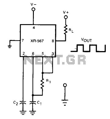
The frequency of the current-controlled oscillator can be doubled by feeding a portion of the square-wave output from pin 5 back to the input at pin 3. This configuration allows the quadrature detector to operate as a frequency doubler,...

Circuit characteristics: A simple phase shift range of 180 degrees, with a practical range of 170 degrees. The circuit is influenced by temperature and is suitable for small power applications in less demanding situations. The circuit operates by utilizing a...
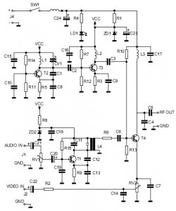
This is the circuit diagram of an audio/video modulator. The circuit converts audio and video signals into a UHF TV signal, allowing a video signal from a camera or other source to be connected to a standard TV set....