
By ASIC delay lamp circuit

The thirty mining lamp control ASIC circuit is designed to manage the operation of a lamp through a simple yet effective delay mechanism. The HL2102 integrated circuit serves as the core component, facilitating the timing and control functions necessary for the lamp's operation. The circuit is particularly useful in applications requiring temporary lighting solutions, such as mining operations where visibility is crucial.
The DIP-8 package of the HL2102 provides ease of integration into various circuit designs, with clearly defined pin functions that allow for straightforward connections to other components. The power supply requirements of 2-6V make the circuit adaptable to different power sources, enhancing its versatility in the field.
The operation of the lamp is initiated through the pressing of the switch (SH), which activates the light (F). The delay feature is a critical aspect, enabling the lamp to remain illuminated for a predetermined duration before automatically turning off. This functionality not only conserves energy but also extends the life of the lamp. The adjustable timing feature is implemented through a potentiometer (RPs) in conjunction with a timing capacitor, providing flexibility in setting the desired delay duration. This can range from a few seconds to several minutes, accommodating various operational needs.
For applications requiring longer delays, the circuit can be modified by adding additional timing capacitors in parallel with the HL2102. This adjustment allows for greater customization of the delay period, making the circuit suitable for a wider range of scenarios.
Powering the HL2102 involves a half-wave rectifier combined with a voltage regulator and filtering capacitor, which ensures stable operation and reliable performance. The choice of components and the design of the circuit emphasize efficiency and simplicity, making it an ideal solution for mining lamp control applications.A thirty mining lamp control ASIC production delay lamp circuit is very simple. Pour in. H L2102 IC Wuxi love core Microelectronics Co., Ltd. (lmp, WV.7W. Wx.sjc.t n) Productio n of light Zhu timed © with integrated circuits, regularly asked to town from child to child BU minutes seconds when wells are free towel concluded, H L2102 standard DIP 8 package, the pin functions shown in Table 31, the power supply voltage range of 2-6V. Figure 85 can be used to get the night l Ke temporary lighting, using just press a button switch SH iLi light F will light up, delay after tens of seconds, the lamp goes out white lines.
The lamp is lit inside called to ask if pressed again SB, lamp F can f/{l against the closure. This circuit since the delay time is short, so the manifold HI.2102 I {, ie first end, song small feet will parallel the timing capacitor H to be adjusted resistance potentiometer RPs value, you can get a few seconds to a few m ten seconds timing. If you ask for more K timing ask, you can HU102 of, feet parallel and then a timing capacitor can be.
I11,2102 for power by the capacitance of T [1 buck, vr) half-wave rectifier, vs regulators and C. Filtering obtained.
Related Circuits
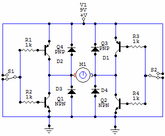
You have 4 transistors, wired as ON OFF switches. Two signal lines allow you to run the motor in one direction, when reversed, the motor runs in the other direction. It's very straightforward to use and build, but be...
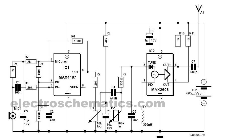
This simple FM wireless microphone transmitter can transmit speech over a short range. It can be used as a simple cordless microphone. The circuit uses two. The FM wireless microphone transmitter is designed for short-range audio transmission, making it suitable...
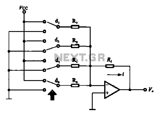
An A/D converter circuit can be represented by a simplified schematic, which illustrates a parallel type A/D converter. The term "median" refers to the number of bits in the digital signal output. The figure displays four A/D converters utilizing...
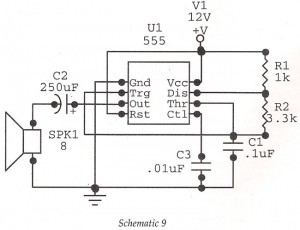
This circuit features an astable oscillator constructed around a 555 timer, generating an alarm tone of 1.8 kHz, which directly drives a speaker. It serves as a fundamental alarm circuit that can be utilized in various projects. Although the...

The circuit has four inputs. The voltage gain between each input and the output is maintained at unity by the relative values of the 470 kΩ input resistor and the 470 kΩ feedback resistor. The described circuit operates as a...
The circuit below is a simple dimmer circuit. A network consisting of R1, R2, VR1, C2, C3, and Q1 controls the triggering angle of the triac by adjusting the variable resistor VR1. The described dimmer circuit employs a TRIAC (Q1)...