
SCR BRY35 For Simple Radio Control Circuit

The SCR BRY35 is a silicon-controlled rectifier designed to facilitate the control of high-power loads through low-power signals. In the context of a simple radio control circuit, the SCR functions as a switch that can be triggered by a radio frequency signal, allowing for wireless control of devices.
The circuit typically consists of a radio receiver module that receives signals from a transmitter. The output from the receiver is connected to the gate of the SCR, which allows it to turn on when a specific signal is detected. Once triggered, the SCR remains in the conducting state until the current flowing through it drops below a certain threshold, known as the holding current.
Key components of the circuit may include:
1. **Radio Receiver Module**: This component receives the radio frequency signals and converts them into a suitable voltage level for triggering the SCR.
2. **SCR BRY35**: This acts as the primary switching device, controlling the load connected to it.
3. **Load**: This could be any high-power device such as a motor or lamp that the circuit is intended to control.
4. **Power Supply**: Provides the necessary voltage and current to the circuit.
The operational efficiency of the circuit can be enhanced by incorporating additional elements such as filtering capacitors to stabilize the power supply and protect against voltage spikes. Additionally, appropriate resistors may be used to limit the gate current to the SCR, ensuring reliable operation without damaging the component.
This simple radio control circuit utilizing the SCR BRY35 is suitable for various applications, including remote-controlled toys, home automation systems, and other devices requiring wireless control. Its design emphasizes simplicity and efficiency, making it an ideal choice for hobbyists and professionals alike.The following circuit shows about SCR BRY35 For Simple Radio Control Circuit. Features: simple and efficient receiver for operating:(starter .. 🔗 External reference
Related Circuits
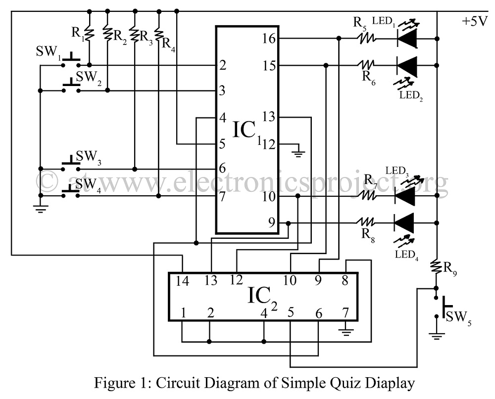
A simple quiz display is constructed using two TTL ICs: the 7445 and the 7420. It indicates which switch is pressed first, accompanied by a circuit diagram. This project represents an interesting and verified game concept. The circuit utilizes the...
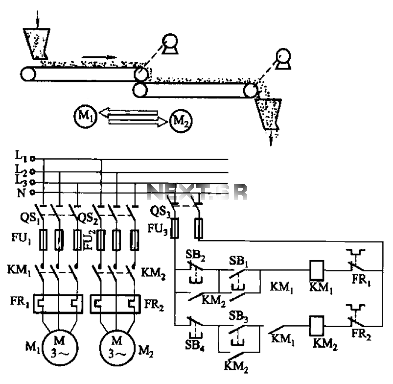
The circuit depicted in Figure 3-86 utilizes a line utilization time relay to control two motors, starting one before the other after an initial stall. The time relay KTi can be adjusted to modify the starting interval of the...
The IC1A operational amplifier is configured as an inverting amplifier, with its gain determined by a three-way switch that connects different resistor values in parallel to resistor R4. This input stage is succeeded by an active three-band tone control...
PID-Control with 68HC11. STEPPER CONTROL. 68HC11 read encoder. High accuracy RPM-measurement with 68HC11. The encoder is connected to PORTA PA0 and PA1. The board must be in BOOTSTRAP MODE (tested with Loggyboard). The circuit utilizes a 68HC11 microcontroller for implementing...
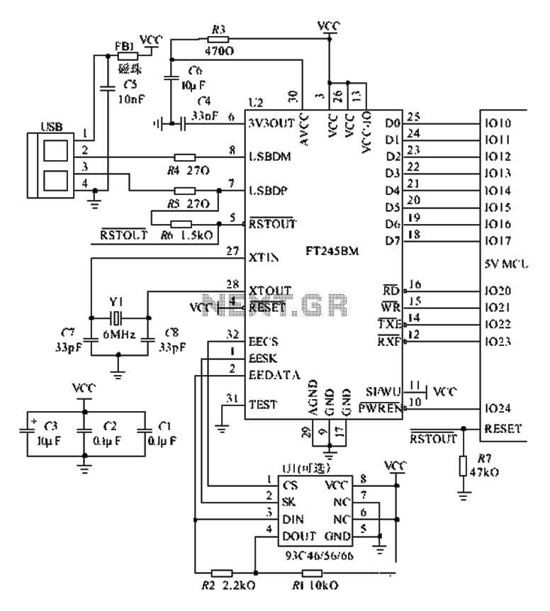
The FT245BM typical hardware circuit operates in bus-powered mode and employs a power-on reset mechanism to initialize the device. The clock circuit can be implemented using a 6 MHz crystal oscillator module or a combination of a 6 MHz...
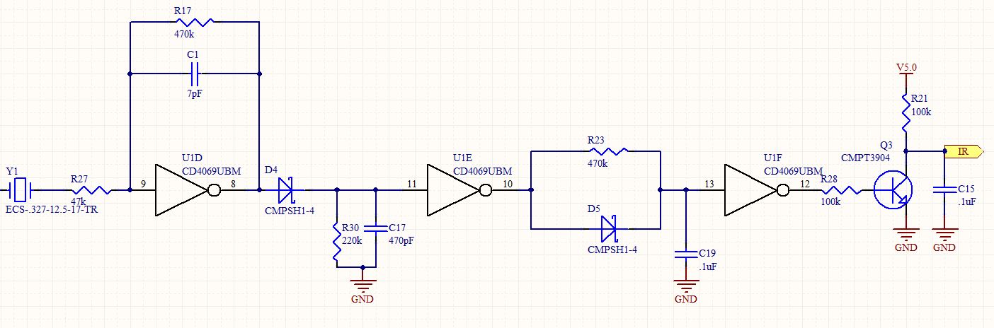
This is a follow-up to an earlier post regarding a specific circuit schematic. The circuit is designed to operate at a supply voltage of 5V, and testing has confirmed that the original device functions correctly at this voltage. A...