
cable tv signal booster amplifier

The cable TV signal booster amplifier circuit is structured to improve the quality and reliability of cable television signals, particularly in areas where signal strength is weak or prone to interference. The use of 75 Ohm coaxial cables ensures optimal impedance matching, which is crucial for minimizing signal loss and maximizing performance.
Transistor Q1, as the primary amplification component, is selected for its high-frequency response and low noise characteristics, which are essential for maintaining signal integrity at the frequencies of interest. The configuration of Q1 is typically a common-emitter amplifier, providing significant voltage gain. Transistor Q2, configured as an emitter follower, serves to buffer the output of Q1, presenting a low output impedance to the subsequent stages or load. This configuration helps isolate the amplifier from the load, ensuring that the gain remains stable regardless of variations in load impedance.
The circuit's gain of 20 dB or more indicates that it can effectively increase the amplitude of weak signals, making it suitable for applications where long cable runs or multiple splitters may attenuate the signal strength. The low current consumption of 20 mA highlights the efficiency of the design, allowing it to operate with minimal power requirements, which is particularly advantageous in portable or battery-operated applications.
Overall, this cable TV signal booster amplifier circuit is an essential component for enhancing cable television reception, ensuring that users receive a clear and consistent signal for optimal viewing experiences. Proper implementation and housing within a metal case also contribute to reducing electromagnetic interference, further improving performance.This is a schematic of a cable TV signal booster amplifier circuit which can be used to amplify or boost the signal of cable TV system. Use 75 Ohm coaxial cables at the input and output of the circuit and fit the circuit in a metal case.
The bandwidth of the circuit is up to 150MHz. Transistor Q1 is used to amplify the signal and Q2 is working as an emitter follower. The circuit will provide gain of 20dB or more. The current consumption of the circuit is only 20mA. 🔗 External reference
Related Circuits
This delay can be used in power amplifiers to prevent the fuses from failing when the amplifier is turned on. The circuit is very simple with a relay that is turned on when C2 and C3 are charged. If...
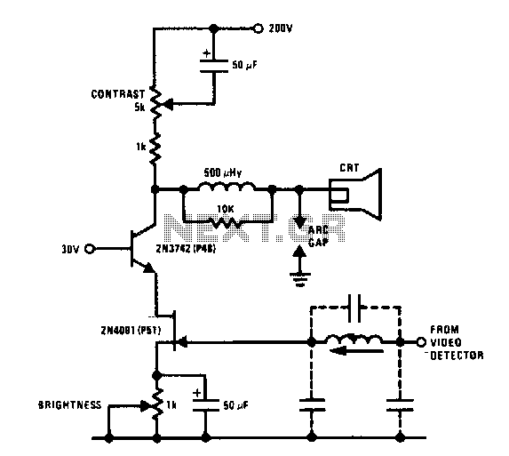
The JFET-bipolar cascode circuit will provide full video output for the CRT cathode drive. Gain is about 90. The cascode configuration eliminates Miller capacitance problems with the 2N4091 JFET, thus allowing direct drive from the video detector. An m-derived...
The original description discusses an application that is reputed for its high-quality sound. This superior sound quality is attributed to the operation of the entrance transistors at Class A. The sound quality is largely dependent on IC1, which needs to...
The preamp circuit is completely conventional, and by necessity is AC coupled throughout. The artificial earth is derived by two resistors (R1 and R2), which will set the "earth" at exactly 1/2 the supply voltage. This is nominally 13.8V...
The circuit depicted in the figure is a generator that includes an oscillator, a voltage follower, a zero amplitude adjustment, and a zero shift circuit. It is utilized as a self-balancing recorder for testing signals. The output signal ranges...

This voltage booster circuit for driving one or more white LEDs utilizes a 555 timer as its main component. The timer, designated as IC1, operates as a resettable astable multivibrator with R1, R2, and C2 serving as the timing...