
Power Supply for the 8051 Microcontroller

The power supply circuit described is essential for providing a stable and reliable voltage to electronic components within a project. The circuit begins with a 0-12V, 500 mA transformer, which steps down the AC mains voltage to a lower AC voltage suitable for further processing. The primary winding of the transformer is connected to the mains supply through an on/off switch, allowing for easy control of power to the circuit. Additionally, a fuse is included in series with the primary winding to protect against overloads and short circuits, ensuring safety and preventing damage to the transformer and the circuit.
The secondary winding of the transformer outputs 12V AC, which is then rectified by a bridge rectifier composed of diodes. This rectification process converts the alternating current (AC) into direct current (DC). The output of the rectifier is a pulsating DC voltage, which is not suitable for most electronic applications without further smoothing.
To smooth the output and reduce ripple voltage, filtering capacitors are connected across the output of the rectifier. These capacitors charge up during the peaks of the pulsating DC and discharge during the troughs, effectively providing a more constant DC voltage. The choice of capacitance value is crucial, as it determines the level of ripple voltage and the response time of the power supply under varying load conditions.
Following the smoothing stage, a voltage regulator is employed to provide a stable output voltage. In this case, an IC 7805 voltage regulator is utilized, which outputs a regulated +5V DC from the smoothed voltage. The 7805 regulator is capable of supplying up to 1A of current, making it suitable for powering various low-power electronic devices. It features built-in thermal overload and short-circuit protection, enhancing the reliability of the power supply.
Overall, this power supply design ensures that the circuit receives a consistent voltage, which is crucial for the proper operation of sensitive electronic components. The integration of a transformer, rectifier, filter capacitors, and a voltage regulator creates a robust power supply solution for a variety of electronic projects.The power supply section is the important one. It should deliver constant output regulated power supply for successful working of the project. A 0-12V/500 mA transformer is used for this purpose. The primary of this transformer is connected in to main supply through on/off switch& fuse for protecting from overload and short circuit protection. The secondary is connected to the diodes to convert 12V AC to 12V DC voltage. And filtered by the capacitors ,Which is further regulated to +5v, by using IC 7805. 🔗 External reference
Related Circuits
It is a simple circuit regulated power supply, based on the known LM 723, that drives a transistor Q1 [2N3055]. The regulation of voltage, of expense becomes with potentiometer R1 from 0v-30v DC roughly. In order to achieve 30...
Construct different power conversion circuits using an Arduino microcontroller. The Arduino microcontroller serves as a versatile platform for developing various power conversion circuits. These circuits can include DC-DC converters, AC-DC converters, and other forms of power management systems. The flexibility...

Fast rise-time high-voltage pulses have various applications, including EMC testing and device characterization. The circuit outlined here is a simple, cost-effective solution designed for the latter purpose. It can generate pulses ranging from 0 to 1000 V with currents...
220 watts Uninterruptible Power Supply. Refer to the designated page for an explanation of the related circuit diagram for this power supply. The 220 watts Uninterruptible Power Supply (UPS) is designed to provide reliable backup power during outages, ensuring that...
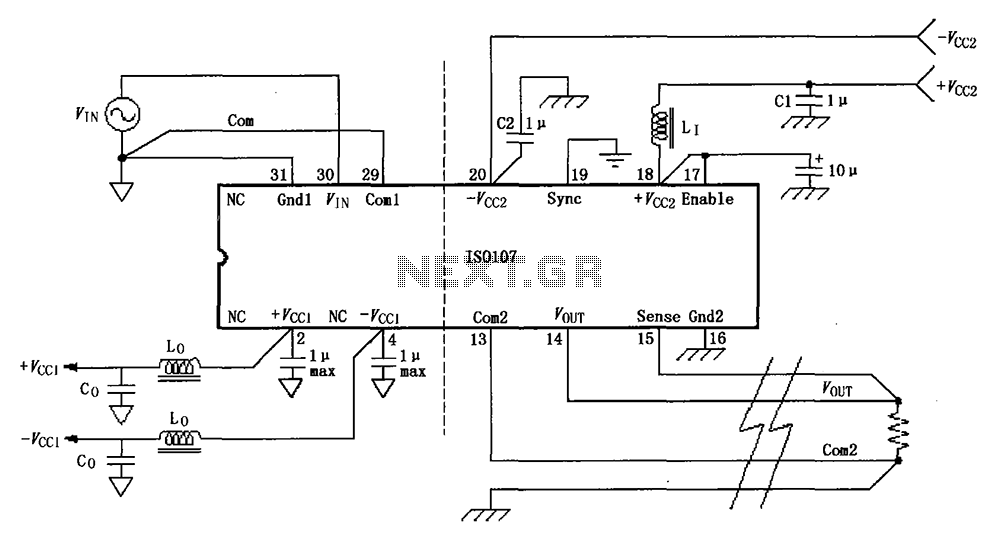
The basic connection circuit for the ISO107 signal and power supply is illustrated. Each power supply terminal must include a bypass filter. If the output current from the isolated power supply exceeds 15 mA, it is advisable to utilize...
The following circuit illustrates a battery-powered burglar alarm sensor circuit. Features include foil tape and passive infrared sensors (PIRs), as well as magnetic reed contacts. This battery-powered burglar alarm sensor circuit is designed to provide an effective security solution for...