
The Metal Detector Circuit

The described circuit operates as a basic oscillator, utilizing a transistor in conjunction with an LC circuit to generate oscillations at a specific frequency. The inductor, functioning as the search coil, is responsible for detecting metal objects by generating a magnetic field. When a metal object, such as gold, enters this field, it alters the inductance, which in turn affects the oscillation frequency of the circuit. The feedback loop formed by the 1n capacitor is crucial for maintaining the oscillation, as it allows the circuit to self-regulate and react to changes in the environment.
The design's simplicity is an advantage, as it provides a cost-effective solution for basic metal detection applications. However, it is important to note that this circuit does not possess the capability to discriminate between different metals. For users seeking to identify gold specifically, more advanced circuitry and signal processing techniques would be necessary. These could involve the use of additional components such as operational amplifiers, microcontrollers, or specialized algorithms for frequency analysis.
In summary, while this circuit serves as a foundational oscillator for metal detection, its limitations must be acknowledged. The interplay between the inductor, capacitor, and transistor creates a dynamic system that responds to external stimuli, but it lacks the sophistication required for precise metal discrimination.This design has not been called a GOLD detector as this name has been left for the more complex detectors that actually discriminate been gold and other metals. There is an enormous difference between detecting gold and ordinary metals (called base metals). How the detector work The circuit is an oscillator and the way it keeps oscillating is due to positive feedback. This is the case with all oscillators and the component that provides the feedback is the 1n capacitor between the collector and emitter of the transistor. It may seem unusual that the transistor can be turned on via the emitter to keep it oscillating, but in fact it does not matter if the emitter or base receives a signal as the important factor is THE VOLTAGE DIFFERENCE between these two terminals.
If the base is kept fixed and the emitter voltage is reduced, the transistor sees a higher voltage between the base and emitter and it is turned ON harder. If the voltage on the emitter increases, the transistor turns OFF as the difference between the two is reduced.
This is exactly what happens in this circuit. The 1n capacitor between the collector and emitter influences the voltage on the emitter to turn the transistor on and off. It does this by constantly monitoring the voltage on the tuned circuit and passing the change to the emitter.
In this project, the TUNED CIRCUIT is the parallel components consisting of the inductor (the search coil) and the 1n capacitor across it. This is called an LC circuit in which the L is the inductance of the inductor in Henries (or mH or uH) and C is the capacitance of the capacitor in Farads (or uF or nF or pF).
We start when the transistor turns ON and allows a pulse of energy to enter the tuned circuit (later you will see how the transistor turns on). The pulse of energy (current) starts by trying to entering both the coil and capacitor. You would think the coil has the smallest resistance but the capacitor is uncharged and presents a theoretical zero resistance and begins to charge.
When a small voltage appears across it, you would think the coil would become the least resistance as it consists of only a few turns of copper wire. 🔗 External reference
Related Circuits
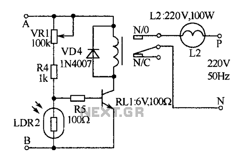
The receiver, as depicted in the figure, assists patients in avoiding missed audio signals during the daytime. The receiver operates independently, and the lighting will automatically turn off. At night, the lighting signal receiver activates simultaneously with the patient's...
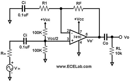
All the capacitors are present to block DC signals; however, the values of capacitance are crucial, and it is necessary to determine the value of Co. Rin denotes the source resistance, which is not an integral part of the...
The section of the 1996 Ford Windstar wiring diagram includes details on power distribution, common connections, rear circuits, ignition systems, the fuse panel, battery connections, instrument illumination, radio wiring, left rear speaker connections, remote headphone module, solid-state components, and...
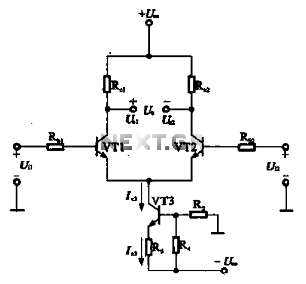
A constant current source is utilized in the differential amplifier circuit, which includes an emitter resistor. In this configuration, an increase in the output voltage (Ua) is not desirable. To ensure that Ua remains stable, the supply voltage (Ucc)...
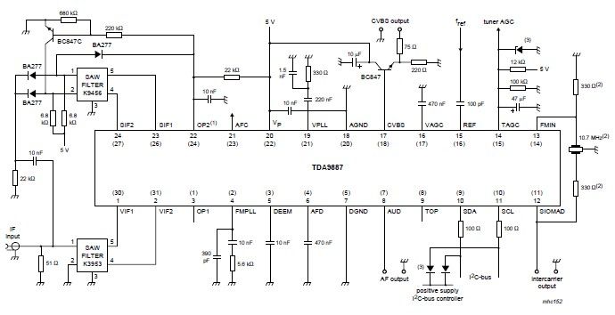
The integrated circuit (IC) is a multistandard vision and sound intermediate frequency (IF) phase-locked loop (PLL) demodulator that operates without the need for alignment. It supports multiple standards, including PAL, SECAM, and NTSC, and is capable of processing both...
The diagram illustrates a human infrared remote sensing lamp circuit. It utilizes the trace infrared heat emitted by humans to control the lamp's operation, allowing it to turn on or off remotely. This human infrared remote sensing lamp features...