
Capacitor charging and discharging

The experiment described involves the use of large-value electrolytic capacitors, which are crucial for creating slow time constants in RC (resistor-capacitor) circuits. These capacitors are distinguished by their sensitivity to polarity, which must be respected to prevent catastrophic failure. The circuit's design allows for the measurement of voltage changes across the capacitor over time, demonstrating the exponential charging behavior characteristic of RC circuits.
The time constant (τ) is a key parameter in this experiment, defined as the product of resistance (R) and capacitance (C). For example, in a circuit with a 1 kΩ resistor and a 1000 µF capacitor, the time constant is calculated to be 1 second. This time constant indicates the duration required for the voltage across the capacitor to reach approximately 63.2% of its maximum value. The gradual rise in voltage can be monitored using a voltmeter, and the experiment can be enhanced by plotting the voltage against time to visualize the charging curve.
To achieve a longer time constant, one approach is to increase the resistance in the circuit. This can be accomplished by connecting multiple resistors in series, thereby increasing the total resistance. Alternatively, increasing the capacitance by connecting capacitors in parallel can also extend the time constant. The experiment encourages exploration of various configurations of resistors and capacitors to observe the effects on the charging rate.
Proper handling of the capacitors is essential, as incorrect polarity can lead to failure, often resulting in explosive outcomes. Therefore, care must be taken to ensure that the negative terminal of the capacitor is connected to the negative side of the battery. The discharging phase of the experiment mirrors the charging phase, with the voltage initially jumping to the battery voltage and then gradually decreasing upon opening the switch.
Overall, this experiment serves as an educational platform to explore the principles of RC circuits, the behavior of capacitors under different configurations, and the critical importance of adhering to polarity guidelines in the use of electrolytic capacitors.Large-value capacitors are required for this experiment to produce time constants slow enough to track with a voltmeter and stopwatch. Be warned that most large capacitors are of the "electrolytic" type, and they are polarity sensitive!
One terminal of each capacitor should be marked with a definite polarity sign. Usually capacitors of the size specified have a negative (-) marking or series of negative markings pointing toward the negative terminal. Very large capacitors are often polarity-labeled by a positive (+) marking next to one terminal. Failure to heed proper polarity will almost surely result in capacitor failure, even with a source voltage as low as 6 volts. When electrolytic capacitors fail, they typically explode, spewing caustic chemicals and emitting foul odors.
Please, try to avoid this! Build the "charging" circuit and measure voltage across the capacitor when the switch is closed. Notice how it increases slowly over time, rather than suddenly as would be the case with a resistor. You can "reset" the capacitor back to a voltage of zero by shorting across its terminals with a piece of wire. The "time constant" ( ) of a resistor capacitor circuit is calculated by taking the circuit resistance and multiplying it by the circuit capacitance.
For a 1 k © resistor and a 1000 µF capacitor, the time constant should be 1 second. This is the amount of time it takes for the capacitor voltage to increase approximately 63. 2% from its present value to its final value: the voltage of the battery. It is educational to plot the voltage of a charging capacitor over time on a sheet of graph paper, to see how the inverse exponential curve develops. In order to plot the action of this circuit, though, we must find a way of slowing it down. A one-second time constant doesn`t provide much time to take voltmeter readings! We can increase this circuit`s time constant two different ways: changing the total circuit resistance, and/or changing the total circuit capacitance.
Given a pair of identical resistors and a pair of identical capacitors, experiment with various series and parallel combinations to obtain the slowest charging action. You should already know by now how multiple resistors need to be connected to form a greater total resistance, but what about capacitors This circuit will demonstrate to you how capacitance changes with series and parallel capacitor connections.
Just be sure that you insert the capacitor(s) in the proper direction: with the ends labeled negative (-) electrically "closest" to the battery`s negative terminal! The discharging circuit provides the same kind of changing capacitor voltage, except this time the voltage jumps to full battery voltage when the switch closes and slowly falls when the switch is opened.
Experiment once again with different combinations of resistors and capacitors, making sure as always that the capacitor`s polarity is correct. 🔗 External reference
Related Circuits
Building battery boxes for the Speedster. Although this topic may not seem thrilling, builders converting vehicles to electric drive often discover that the process of making a car run on battery power is relatively straightforward. However, about 50% of...
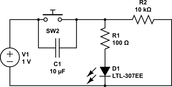
Understand why the LED does not light up, as the capacitor appears to be bypassing the switch. When the capacitor is fully charged, it does not conduct electricity. Although the individual is a beginner, after 20 hours of studying...
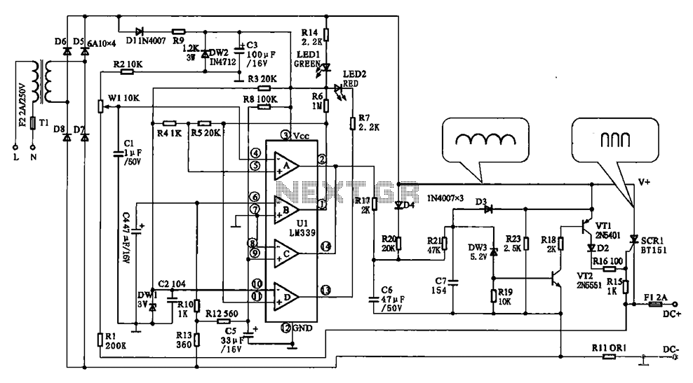
The Chizuru 100Hz channel frequency pulse charging circuit for electric bike batteries is designed to manage the charging process efficiently. It features a step-down transformer (Tl) and a bridge rectifier formed by diodes D5 to D8. The output ripple...
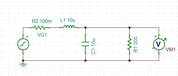
An inductor is used in series with a decoupling capacitor, forming a series LC circuit. One of the characteristics of LC circuits is their resonant frequency. A model of this LC circuit was created with a purely resistive load...
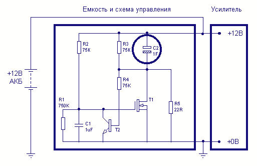
One-farad capacitors require some care. It's common knowledge that they must be pre-charged with a current-limiting resistor before plugging in. It is less common knowledge that those fifty-dollar smart cap controllers are in fact very simple devices, two dollars...
Instructions for electric motor start-run capacitors include the use of starting capacitors for air conditioner compressor motors and other electric motors like pumps. This involves diagnostic checks for start or run capacitors, including how to use a volt-ohm meter...