
capacitor Explaining a car voltage regulator circuit

The LM7805 voltage regulator is a popular choice for providing a stable 5V output from a higher input voltage, such as the 12V typically found in automotive applications. The two capacitors on either side of the regulator serve distinct functions that contribute to the overall performance and stability of the circuit.
On the input side, the 0.1 µF capacitor acts as a high-frequency bypass capacitor. Its role is to filter out high-frequency noise and transients that may be present on the input voltage line, ensuring that the regulator receives a clean, stable input. This capacitor is typically ceramic, which provides low equivalent series resistance (ESR) and inductance, making it effective for high-frequency applications.
The 470 µF capacitor, also located on the input side, is a bulk capacitor that provides energy storage. It helps to smooth out any voltage fluctuations caused by load changes or noise from the power supply. This larger capacitor can handle lower frequency variations and provides a reservoir of charge that the regulator can draw from when needed, thus improving transient response.
On the output side, the 0.1 µF capacitor again serves as a high-frequency bypass capacitor, ensuring that the output voltage remains stable and free from high-frequency noise that could affect the microcontroller's operation. The 470 µF capacitor on the output side similarly helps to stabilize the output voltage by providing additional charge storage, ensuring that the microcontroller receives a consistent voltage supply, especially during periods of high current draw.
In summary, the combination of a small capacitor (0.1 µF) and a larger capacitor (470 µF) on both the input and output sides of the LM7805 regulator is a common practice in electronic design. This configuration enhances the stability and performance of the voltage regulation, allowing the Atmel AVR microcontroller to operate reliably within its specified voltage range.Regulating ~12V from the car battery to 5V used by Atmel AVR microcontroller. Why are there two capacitors on each side of linear regulator LM7805 This answer to another question might be the answer I`m looking for, but I`m not sure about it. If this answer is related to my question and the use of two capacitors is to reduce resistance and inductance, why are such different capacitor ratings used (0.
1 µF and 470 µF) 🔗 External reference
Related Circuits
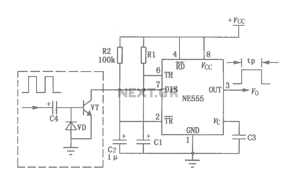
This circuit was originally a type of power-delay control circuit, where the delay time is determined by the timing elements R1 and C1. Additionally, with the inclusion of a "watchdog" circuit, it can be utilized as a monitoring circuit...
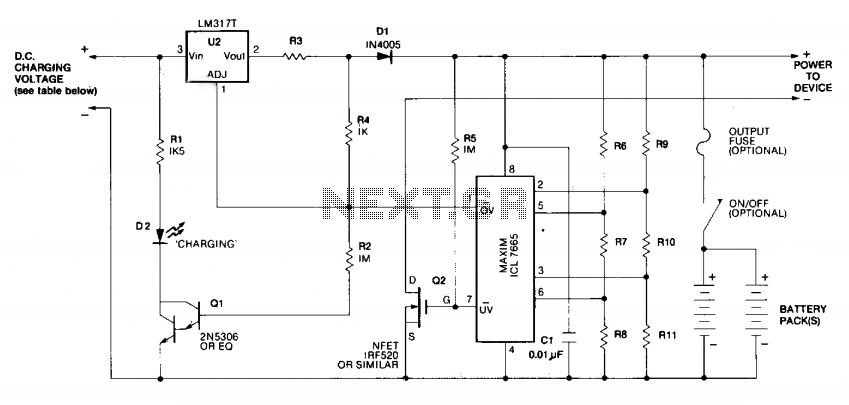
Charging is achieved using a constant current of 60 mA for AA cells, reaching a cutoff voltage of 2.4 V per cell, at which point the charging process must be terminated. The charging system is designed for multi-cell battery...
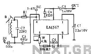
This figure illustrates the schematic of the LM567 SCA broadcast reception information machine. The LM567 serves as a narrow-band phase-locked loop designed primarily for SCA broadcast demodulation. The configuration includes a potentiometer (W) and capacitor (C6) that determine the...
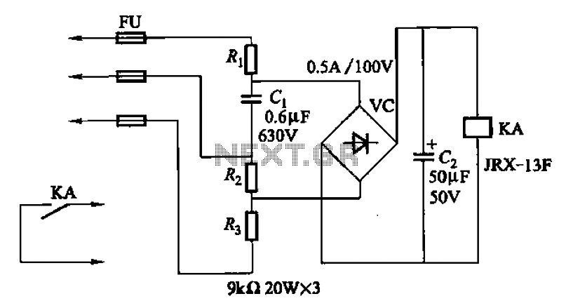
A capacitor C1 and resistors R1-R3 form a negative sequence voltage filtration device. The resistors and capacitors must meet the following requirements: R1, R2, R3 = 5.5/C1 (KN). The relationship between the resistance and capacitance values is arbitrary. Capacitor...
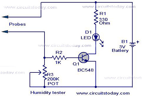
A simple humidity tester circuit using only an LED, a transistor, and a few resistors is explained with a clear circuit schematic. The humidity tester circuit is designed to provide a visual indication of humidity levels using basic electronic components....
This device can be used against aggressive animals or attackers; however, it is important to note that it may be illegal in certain states. The device in question is designed for personal protection and can serve as a deterrent against...