
Lithium charger circuit

The charging system described operates under a constant current method, which is a common approach for charging rechargeable battery cells. The specified charging current of 60 mA is optimal for AA cells, ensuring that the batteries are charged efficiently without overheating or damaging the cells. The cutoff voltage of 2.4 V per cell is critical, as exceeding this voltage can lead to overcharging, which may reduce the lifespan of the batteries or even cause safety hazards.
In the context of multi-cell battery packs, the system is capable of charging configurations ranging from 2 to 6 cells connected in series. This series connection is essential for achieving the necessary voltage levels for various applications. For instance, with 6 cells in series, the total voltage can reach up to 15.6 V (6 x 2.6 V), making it suitable for powering devices that require higher voltage inputs.
It is important to highlight the necessity for all cells in the pack to be at the same state-of-charge before charging begins. This ensures that each cell receives an equal amount of charge, preventing any single cell from becoming overcharged or undercharged, which could lead to imbalances within the pack. Such imbalances can lead to reduced performance and lifespan of the battery pack.
The charging system may also include additional features such as temperature monitoring and safety cutoffs to enhance the reliability and safety of the charging process. Implementing these features can help prevent thermal runaway conditions and ensure that the batteries are charged within safe operating limits. Overall, this charging system is designed to provide efficient and safe charging for multi-cell battery configurations while maintaining the integrity and performance of the individual cells.Charging is accomplished with a constant current of 60 mA for AA cells to a cutoff voltage of 2.4 V per cell at which point the charge must be terminated. The charging system shown is designed for multi-cell battery packs of 2 to 6 series-connected cells or series/parallel arrangements.
It is essential that all cells assembled in the pack be at an identical state-of-charge (voltage) prior to charging. The maximum upper cut-off voltage is 15.6 volts (6 ? 2.6 V).
Related Circuits
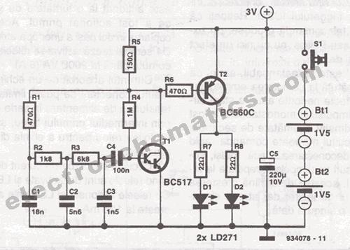
This infrared transmitter is designed for use with an infrared receiver. It operates using either two 1.5V batteries or a 3V lithium battery, allowing for a compact infrared communication system. The infrared transmitter circuit typically consists of an infrared LED,...
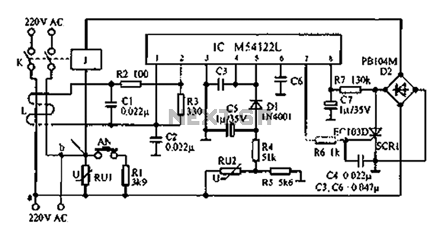
The multifunction leakage protection switch utilizes the Nissan ASIC M54122L. It is designed to serve as a multi-function leakage protection switch. In the event of leakage or electric shock, the magnetic field generated through the inductor line and neutral...
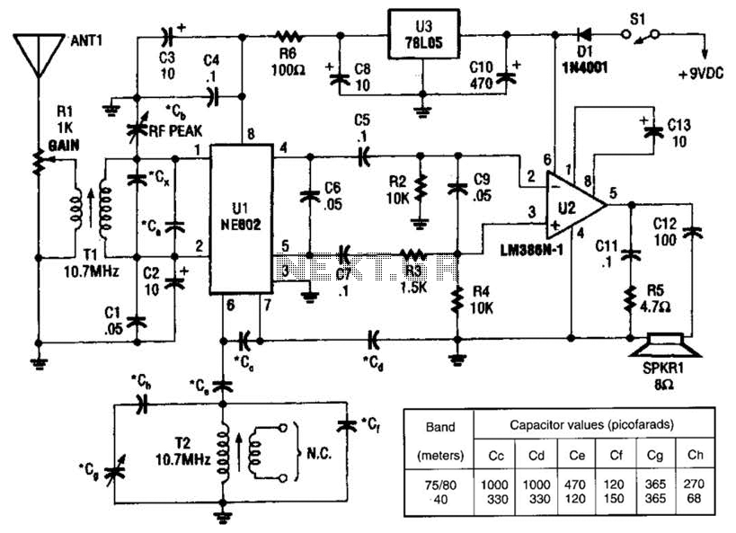
An NEC602 is utilized as a mixer with a zero intermediate frequency (IF) output, while U2 functions as an audio amplifier. This receiver is mainly designed for single sideband (SSB) and continuous wave (CW) signals. T1 and T2 are...
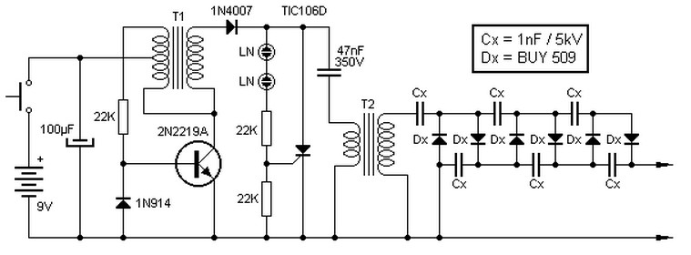
This high voltage source consists of an inverter built around a transistor that generates pulses of 150V. These pulses are supplied to an inverter made of a thyristor and a capacitor, which is connected in series with transformer T2....
The circuit is based on a single operational amplifier integrated circuit designed to produce a modular preamplifier that operates in Class A configuration. The modular preamplifier circuit utilizes a single operational amplifier (op-amp) integrated circuit, which serves as the primary...
This circuit was built to charge two series lithium cells (3.6 volts each, 1 Amp Hour capacity) installed in a portable transistor radio. The circuit is designed to efficiently charge two lithium-ion cells connected in series. Each cell has a...