
Car Anti-Theft Wireless Alarm
When an intruder attempts to drive the car and moves it a few meters away from the car porch, the radio link between the car (transmitter) and the alarm (receiver) is interrupted. As a result, the FM radio module generates hissing noise. These hissing AC signals are coupled to the relay switching circuit via an audio transformer. The AC signals are then rectified and filtered by diode D1 and capacitor C8, producing a positive DC voltage that provides forward bias to transistor T2. Consequently, transistor T2 conducts, pulling the base of relay driver transistor T3 to ground level. This deactivates the relay, and the alarm connected through the normally closed contacts of the relay is activated. Even if the intruder disconnects the transmitter from the battery, the remote alarm remains active because the absence of the signal causes the receiver to continue producing hissing noise at its output. Therefore, the burglar alarm is fool-proof and highly reliable.
The circuit operates effectively by utilizing a simple yet efficient design. The transmitter, which is typically a miniaturized FM transmitter, is designed to operate within a specific frequency range that corresponds to the receiver's tuning. The use of the CXA1019 module allows for a compact solution that simplifies the overall design while ensuring reliable communication between the transmitter and receiver.
The relay driver circuit is crucial for the operation of the alarm system. Transistor T3 acts as a switch that controls the relay, which in turn activates the alarm. The 10k resistor R5 is essential for providing the correct biasing to T3, allowing it to function effectively when the conditions are met.
Additionally, the audio transformer plays a significant role in coupling the hissing noise generated by the FM module to the relay switching circuit. This ensures that the alarm is triggered appropriately in the event of a breach. The rectification and filtering process performed by diode D1 and capacitor C8 is vital for converting the AC signals into a usable DC voltage that can control the transistors.
Overall, the design of this anti-theft wireless alarm circuit demonstrates a practical application of radio frequency technology in automotive security, providing a reliable means of protecting vehicles from theft. The system's simplicity and effectiveness make it an attractive option for vehicle owners seeking enhanced security measures.This alarm circuit is an anti- theft wireless alarm can be used with any vehicle having 6- to 12-volt DC supply system. The mini VHF FM radio-controlled, FM transmitter is fitted in the vehicle at night when it is parked in the car porch or car park.
The receiver unit of the wireless alarm uses an CXA1019, a single IC-based FM radio module, which is freely available in the market at reasonable rate, is kept inside. Receiver is tuned to the transmitter`s frequency. When the transmitter is on and the signals are being received by FM radio receiver, no hissing noise is available at the output of receiver. Thus transis- tor T2 (BC548) does not conduct. This results in the relay driver transistor T3 getting its forward base bias via 10k resistor R5 and the relay gets energised.
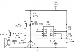
The following is a schematic drawing: When an intruder tries to drive the car and takes it a few metres away from the car porch, the radio link betw- een the car (transmitter) and alarm (receiver) is broken. As a result FM radio module gene-rates hissing noise. Hissing AC signals are coupled to relay switching circ- uit via audio transformer. These AC signals are rectified and filtered by diode D1 and capacitor C8, and the resulting positive DC voltage provides a forward bias to transistor T2.
Thus transistor T2 conducts, and it pulls the base of relay driver transistor T3 to ground level. The relay thus gets de-activated and the alarm connected via N/C contacts of relay is switched on. If, by chance, the intruder finds out about the wireless alarm and disconnects the transmitter from battery, still remote alarm remains activated because in the absence of signal, the receiver continues to produce hissing noise at its output. So the burglar alarm is fool-proof and highly reliable. (Ed: You may have some problem catching the thief, though, if he decides to run away with your vehicle_in spite of the alarm!) We aim to transmit more information by carrying articles.
Please send us an E-mail to wanghuali@hqew. net within 15 days if we are involved in the problems of article content, copyright or other problems. We will delete it soon. 🔗 External reference
Related Circuits
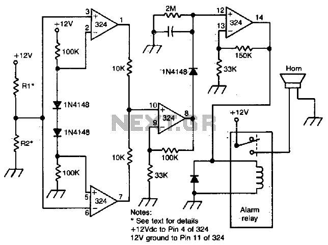
Removing R1 or R2 from the circuit allows a potential thief to break a hidden wire that connects R1 to +12 V and R2 to ground. This action activates the alarm for approximately five minutes. The circuit in question is...
This is a straightforward 12V rechargeable smart battery charger circuit. It can be utilized as a charger for car batteries, inverter batteries, emergency light batteries, and more. An automatic indicator alarm circuit accompanies this battery charger schematic. The primary...
In Fig.1 see a DC current sensing switch, in which the current is applied from an 8 to 16 Volt supply. The R1 value is chosen so that it generates roughly 100 mV at the required trip current. In...
A two-tone generator that is alternately switched ON provides a high/low output similar to that of a traffic vehicle, such as a police car or ambulance. The CD4011 integrated circuit (IC1), which is a quad 2-input NAND gate, functions...
The following circuit illustrates a Sun Up Alarm Light Alarm Circuit Diagram. This circuit is based on the 555 Integrated Circuit (IC). Features include simplicity and cost-effectiveness. The Sun Up Alarm Light Alarm Circuit employs the 555 timer IC in...
The electric car remote control circuit diagram enables the model car to move forward and backward, as well as turn left and right. It is simple and easy to operate. The radio remote control receiver demodulation circuit utilizes TWH9238...
Warning: include(partials/cookie-banner.php): Failed to open stream: Permission denied in /var/www/html/nextgr/view-circuit.php on line 713
Warning: include(): Failed opening 'partials/cookie-banner.php' for inclusion (include_path='.:/usr/share/php') in /var/www/html/nextgr/view-circuit.php on line 713