
Car Battery Charger

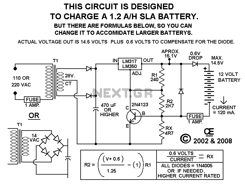
The described charger circuit is designed for efficient charging of lead-acid batteries, providing a straightforward and effective solution for battery maintenance. The primary operational mechanism involves the delivery of a full charging current until the battery's charging current decreases to a threshold of 150 mA. This automatic adjustment is crucial for ensuring that the battery is not subjected to overcharging, which can lead to reduced battery life and potential damage.
Upon reaching the 150 mA threshold, the charger switches to a lower voltage output, allowing for a gentle finish to the charging cycle. This method of tapering off the charge is essential for maintaining battery health, as it prevents excessive gassing and heat generation, which are common issues during the final stages of charging.
The circuit includes an LED indicator that illuminates when the battery is fully charged, providing a clear visual cue to the user that the charging process has concluded. This feature enhances usability, ensuring that users are aware of the battery's status without needing to monitor the charging process continuously.
The design is intended to be powered directly by an external power supply, which simplifies the circuit by omitting components such as a transformer, rectifier, or filter capacitors. However, it is noted that these components can be added if desired, allowing for greater flexibility in various applications or environments where the power supply characteristics may vary.
Thermal management is also an important consideration in this design. The integrated circuit U1, which likely serves as a voltage regulator or control element, will require a heatsink to dissipate heat generated during operation. Proper thermal management ensures the reliability and longevity of the components, especially during extended charging cycles.
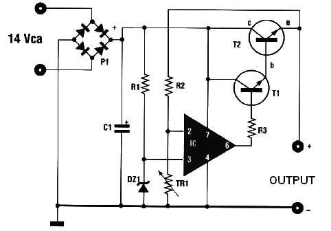
Overall, this charger circuit provides a practical solution for lead-acid battery charging, balancing efficiency, safety, and user-friendliness.This charger will quickly and easily charge most any lead acid battery. The charger delivers full current until the current drawn by the battery falls to 150 mA. At this time, a lower voltage is applied to finish off and keep from over charging. When the battery is fully charged, the circuit switches off and lights a LED, telling you that the cycle has finished. 1. The circuit was meant to be powered by a power supply, which is why there is no transformer, rectifier, or filter capacitors on the schematic. There is no reason why you cannot add these. 2. A heatsink will be needed for U1. 3. To use the circuit 🔗 External reference
Related Circuits
Most mobile chargers lack current and voltage regulation as well as short-circuit protection. These chargers supply unregulated 6-12V DC for charging battery packs. Typical mobile phone battery packs are rated at 3.6V and 650mAh. To enhance battery longevity, it...
In perfect discharge the batteries of lead acid, exists the fear they are destroyed. This circuit makes the work, this detection of discharge, protecting the batteries from destruction. At the discharge the polar voltage of batteries 12V of Lead...
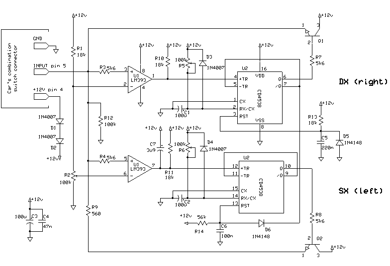
Frequent use of direction indicators is essential for lane changes while driving on motorways. This is typically achieved by maintaining pressure on the indicator switch. The operation of direction indicators, commonly known as turn signals, is crucial for safe driving,...
This automatic battery charger circuit is ideal for charging batteries used in alarm systems that require battery buffering. Caution must be exercised when connecting the battery to ensure correct AC polarity. It is essential to meticulously follow the schematic...
Using this circuit will give good charging results to the gel cell battery used in the metal detector or any other similar and smaller type battery. This charger is both current and voltage regulated. The output is not short...
This circuit will not function unless the battery to be charged is connected with the correct polarity. The voltage of the battery regulates the charger, and when the battery is fully charged, the charger will stop supplying current to...