
Circuit Diagram 6 zone alarm independent

The 6-zone alarm circuit operates by monitoring six distinct zones for security breaches. Each zone is connected to normally closed contacts, ensuring that any interruption in the circuit will trigger the alarm. Zone 1 serves as a timed entry/exit zone, allowing users a brief period to disarm the system upon entry or exit. The remaining zones (2 to 6) are configured for immediate response, enhancing security by ensuring rapid detection of unauthorized access.
Input capacitors C1 to C6 are strategically placed to mitigate radio frequency interference, which is particularly beneficial for installations with long wiring runs. The use of these capacitors helps maintain signal integrity and reduces false alarms caused by electrical noise.
The key switch S1 is a critical component of the system, providing a physical means to set or reset the alarm. The recommendation for a metal key switch is based on durability and security, which are essential in alarm systems. Switch S2 allows for a testing mode, enabling users to verify the functionality of the alarm system without triggering an actual alarm. In this mode, the system is designed to keep the 7-segment display active, providing a visual indication of any opened zones while preventing alarm activation.
The circuit's design incorporates a unique feature where the first zone to trigger the alarm is latched, ensuring that the user is aware of which zone has been compromised. This feature is particularly useful for troubleshooting and maintenance, as it allows for a clear identification of security breaches. Overall, the 6-zone alarm circuit is a robust solution for enhancing security in small environments, providing flexibility in operation and ease of use.Here is 6 zone alarm independent circuit. this circuit suitable for a small office or home environment, it can also be adapted to use a combination lock or keypad to set and reset the alarm. All zones Z1 to Z6 use normally closed alarm contacts. Zone 1 is a timed zone which must be used as the entry and exit point of the building. Zones 2 to 6 are immediate zones, which will trigger the alarm with no delay. Some RF immunity is provided for long wiring runs by the input capacitors, C1 C6. The key switch, S1 acts as the Set and Reset/Unset switch. For best security this should be the metal type switch with a key. Switch S2 is normally used in the run position. However in the test position, this allows a useful walkthrough test of the alarm. In the test position the input of U7A is always low and will not trigger the alarm, also the blanking input is also high, meaning that the 7 segment display is always illuminated. With all zones closed, open any zone, the corresponding number will be shown on the display. Note that if two zones are opened the diplay will not necessarily indicate the correct zone, this is not a fault, just the way the circuit is designed.
When in run mode, the first zone to trigger the alarm is caught and latched and will be displayed until the alarm is reset. Here is a schematic drawing: We aim to transmit more information by carrying articles. Please send us an E-mail to wanghuali@hqew. net within 15 days if we are involved in the problems of article content, copyright or other problems.
We will delete it soon. 🔗 External reference
Related Circuits

This circuit generates the sound of two canaries singing in a cage. Two LM324 quad amplifiers constitute seven oscillators. One oscillator serves as an on/off control, while the remaining six produce the sounds of two canaries. A 9-V supply...
Battery eliminators are circuits that create a DC power supply from AC mains. Essentially, battery eliminator circuits consist of a step-down transformer, rectifier, and voltage regulator. A simple circuit of a multipurpose battery eliminator features various output voltage ranges...

This board layout was created using the SOIC version of a PIC16F627A without drawing the usual schematic first. Most of the part values are etched on the Layout. The SIP resistor packs I used are 10k ohm, some experimentation...
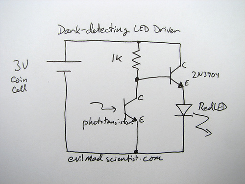
The following circuit illustrates a simple and inexpensive dark-detecting LED circuit. Features include the use of photoresistors, specifically a photocell or LDR, and an LED. This circuit utilizes a light-dependent resistor (LDR) as the primary sensing element. The LDR exhibits...
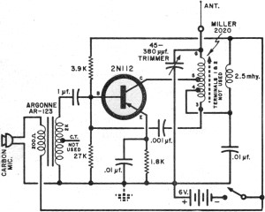
It had been a little over a decade since the invention of the transistor when this article appeared in the August 1959 edition of Popular Electronics. Transistors were still a mystery to many, including engineers, technicians, and hobbyists. Author...
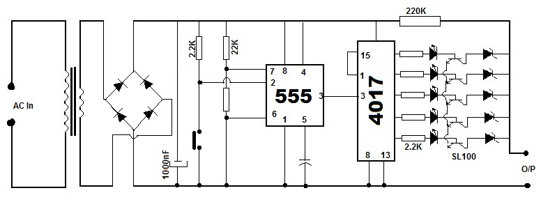
This circuit is a simple 12V DC to 220V AC inverter that produces an AC output at line frequency, specifically 220V AC, or other voltages by selecting transformer T1. The 555 integrated circuit (IC) is configured as a low-frequency...