
Output 85 to 145V adjustable power supply circuit

The circuit described employs the LM317 voltage regulator, which is a versatile component capable of delivering a stable output voltage that can be adjusted according to the requirements of the application. The LM317 operates by maintaining a constant voltage across its output terminals, which can be set to a desired level using external resistors or a potentiometer.
In this configuration, the circuit is designed to provide an adjustable output voltage ranging from 85V to 145V. This is achieved by connecting the adjustment potentiometer (RP) in a manner that allows for fine-tuning of the output voltage. The potentiometer acts as a variable resistor, altering the feedback voltage to the LM317, thus changing the output voltage accordingly.
The inclusion of a thyristor in the circuit serves as a means of controlling the power supply, allowing for presetting of the LM317. This component can handle high voltages and is suitable for applications where the voltage needs to be controlled or switched on and off rapidly. The thyristor's ability to withstand high current and voltage levels makes it an ideal choice for this type of power supply circuit.
The output current of the circuit is limited to a maximum of 1A, which is a typical specification for the LM317. This ensures safe operation and prevents overheating or damage to the regulator and connected components. Proper heat dissipation techniques, such as heatsinking, should be employed to maintain the reliability of the circuit during operation.
Overall, this power supply circuit is suitable for various applications requiring adjustable voltage levels, including testing and powering electronic devices that operate within the specified voltage and current ranges. Careful consideration of component ratings and thermal management will enhance the performance and longevity of the circuit.It uses three-terminal adjustable voltage regulator power supply functions and suspension Electric thyristor presetting the LM317 voltage technology to 85 ~ 145V adjustable output voltage, output current is not greater than 1A. Adjustment potentiometer RP, can change the output voltage.
Related Circuits
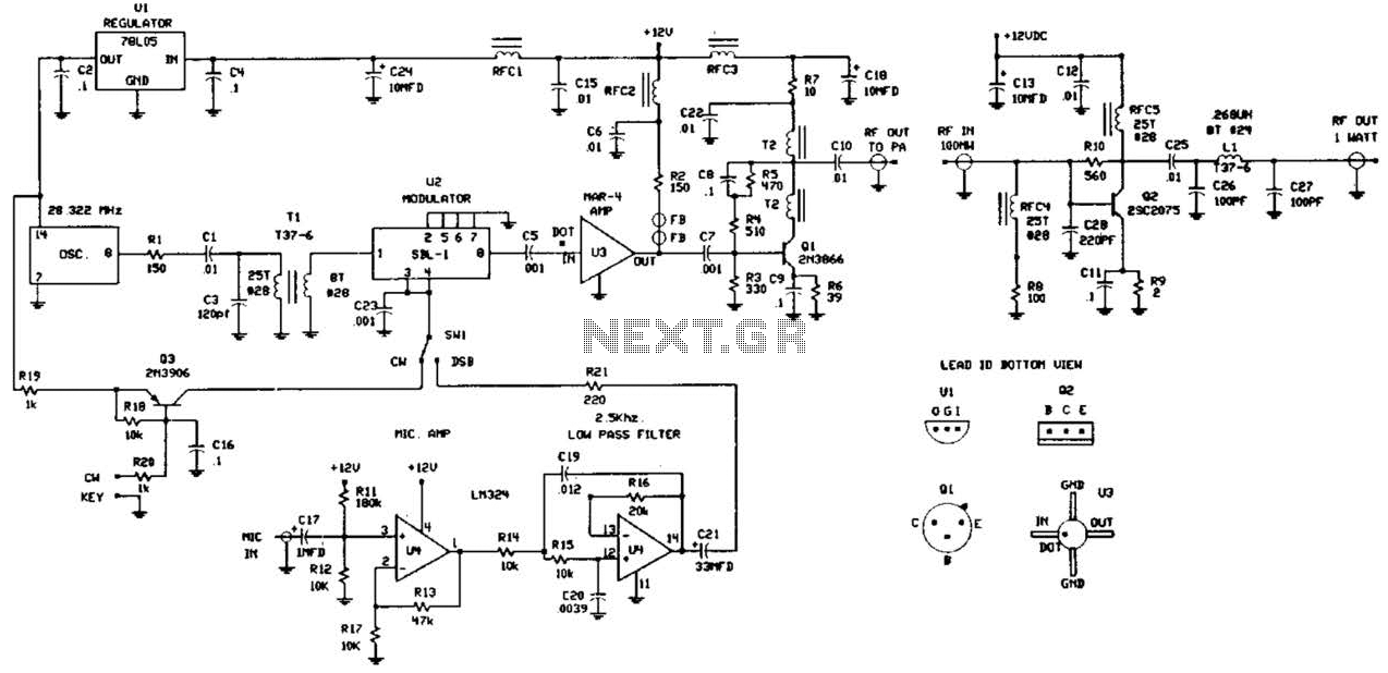
This circuit was detailed in a recent edition of an amateur radio magazine. It enables operation in the 160 to 190 kHz band with a maximum power output of 1 W (license-free) in various modes such as CW, SSB,...
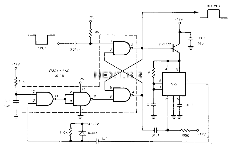
The 555 Timer facilitates a low-loss single-shot circuit and interfaces with the CMOS4011B NAND gate circuit. The standby power consumption is less than 50 µA. When the one-shot circuit is activated, the current consumption is 4.5 mA, and the...
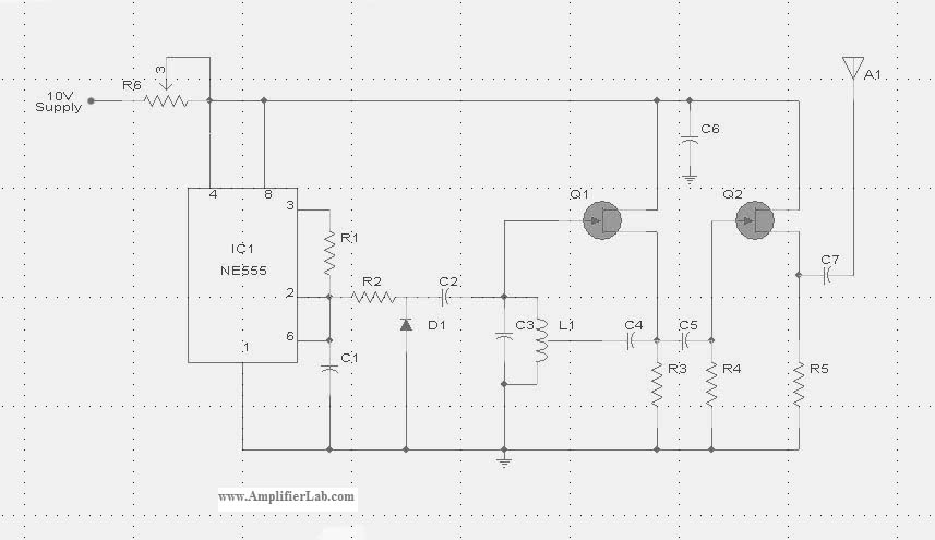
The circuit diagram of the Radio Collar Transmitter is presented here. This circuit is based on the NE555 integrated circuit, which serves as the central component. The Radio Collar Transmitter circuit utilizes the NE555 timer IC to generate a modulated...
The calibration circuit operates in inject mode, generating a square wave output in the audio range, where power harmonics can be detected at several Hertz. In tracking mode, the amplifier detects non-linear operation by filtering a modulated RF signal...
A two-phase servo motor features a field winding and a control winding. When there is a 90° phase difference between the two, it generates rotational torque. A potentiometer connected to the motor shaft measures the voltage difference between the...

This page features a circuit that has twenty open collector outputs that turn on one at a time in a continuous sequential manner. The circuit utilizes the 74LSxx family of TTL integrated logic devices. The circuits are designed to...