
Protectors Circuit on SMPS (power supply) Schematic Diagram
")
The described SMPS circuit operates using three transistors: the C3807 and A1015, which serve as signal transistors, and a power transistor that handles the load. The feedback mechanism is crucial for maintaining the output voltage at a stable level. If the feedback circuit malfunctions, it can lead to an excessive output voltage, which poses a risk to the entire circuit. This situation can result in catastrophic failures, such as the explosion of electrolytic capacitors (elcos) or damage to the printed circuit board (PCB) due to overheating.
In particular, the feedback circuit's failure can cause the power regulator transistor to experience overcurrent conditions. This may occur if the resistor value in the secondary error detector circuit is not appropriately calibrated, leading to delayed feedback response. The resistor, typically rated at 47kΩ, plays a critical role in determining the stability and responsiveness of the feedback loop. If this value is incorrect, it can result in a slow response time, allowing the output voltage to rise to dangerous levels.
Additionally, fluctuations in the input AC voltage can further complicate the situation. A drop in input voltage can lead to increased current through the power regulator transistor, risking damage from overcurrent conditions. The design must account for such variations to ensure reliable operation.
Moreover, if there is a short circuit in the secondary power transistor, it can exacerbate the overcurrent situation, leading to additional damage to the power regulator. Therefore, it is essential to design robust protection mechanisms within the circuit, such as current limiting features or thermal shutdown capabilities, to safeguard against these potential failures.
In summary, careful consideration of the feedback circuit design, component selection, and protective measures is essential in the development of a reliable SMPS that minimizes the risk of component failure and ensures stable operation under varying load conditions.The simplest example SMPS which still uses 3 transistors (C3807, A1015 and power transistors) classic problem that often occurs is: -Problem in the feedback circuit can cause the output voltage B + over so that it can endanger the aircraft as a whole. For example elco erupted, pcb burnt burnt by over-heated, horizontal transistor short. - Problem on feedback circuits may cause power regulator transistor is damaged due to over current transistor (eg, due to the 47k resistor transistor circuit on the secondary error detector value is delayed). - If the input ac voltage drops can cause the power regulator transistor is damaged, due to over current transistor If the secondary there is a power transistor short can cause damage over current regulator.
🔗 External reference
Related Circuits
The image below displays the schematic diagram of the SPI Flash programmer hardware interface. Power for the interface can be supplied using either a 9V DC adapter or a 9V battery. The 74HCT367 integrated circuit (IC) buffers the adjacent...
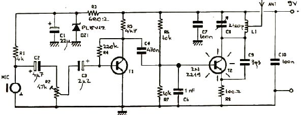
This FM transmitter electronic project operates in the FM band with a transmission power of approximately 250 mW. The circuit is straightforward and utilizes common transistors and electronic components. The T1 transistor, which may be a BC107, BC171, or...
At this voltage regulator prototype the maximum current, with output shortcircuited it was only 0.5 A, so no overheating occurred. In this DC voltage regulator circuit, T1 is for current limitation. As soon as the voltage on the R2...
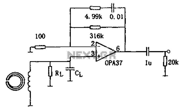
The circuit is a 90s common recorder head amplifier circuit that utilizes the ultra-low noise precision operational amplifier OPA37 as a preamplifier. This circuit is capable of providing standard NAB equalization. At a frequency of 1 kHz, it achieves...
This circuit is designed to operate an electric strike or an electromagnetic lock on a door. It does not control the door's opening or closing but rather activates a small electromagnetic strike that unlocks the door. The opener features...
This simple stereo encoder circuit schematic is built with two ICs, MMC4066E and MMC4047, along with one transistor, BC547B. The audio output is taken from pins 2 and 3 of IC1. The stereo encoder circuit utilizes the MMC4066E, which is...