
CB transmitter

L1 and L2 serve as the primary inductors in the circuit, providing necessary magnetic coupling for signal transmission. The choice of copper as the wire material ensures minimal resistive losses, while the specified diameter allows for efficient inductance values to be achieved. The plastic support serves to maintain the integrity of the coil structure, preventing any deformation that could affect performance.
The aerial (ANT1) is crucial for effective transmission and reception of CB signals. While a temporary wire may suffice for initial testing, utilizing a properly designed aerial is essential for optimal performance, minimizing signal degradation, and protecting the transmitter from potential overload conditions caused by reflections or standing waves.
S2, the channel selection switch, allows the user to choose between different operational frequencies. The mechanical linkage to S1 enhances user experience by allowing simultaneous channel changes, which is particularly useful in dynamic communication environments.
The microphone connection is integral to the system, providing audio input for transmission. The multimeter serves as a diagnostic tool, enabling the user to monitor output levels. An increase in the multimeter reading by 30-35% during operation indicates proper functionality of the audio input stage, suggesting that the system is effectively converting sound waves into electrical signals for transmission. This feedback loop is essential for ensuring reliable communication in practical applications.L1, L2 Wires of coper (smaltwme`na) with diameter 0, 4mm wrapped in plastic support of diameter 6-7mm of perjstrofjkoy` core. For the L1 you wrap 13 coils. For the L2 you wrap 4 coils. (As in the receptor CB. ) ANT1 Aerial for CB (For the trials is enough a piece wire of few metres but better connects a regular aerial so that does not have many stagnantly and burns the transmitter).
S2 Switch of choice of channel. It has so much places, those who also the channels that you want pja`nete. (Kaly`tera he is mechanically connected with the S1 of receptor for simultaneous change of channels). 4. We connect the microphone and speaking we observe the clue in the multimeter. If all have become right will be supposed the tendency, speaking, to go up roughly 30-35%. 🔗 External reference
Related Circuits

The schematic for this project is deceptively simple compared to the complexity of the circuit's operation. The two signals generated are mixed together at the base of transistor T2, and once it exits the collector of the transistor, the...
The RF oscillator utilizes inverter N2 and a 10.7 MHz ceramic filter to drive the parallel combination of inverters N4 to N6 through inverter N3. Since these inverters are connected in parallel, the output impedance is low, allowing direct...
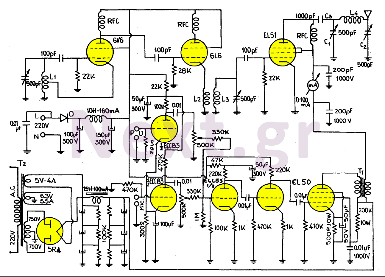
This transmitter, equipped with a quality antenna and utilized under optimal conditions, can achieve a range exceeding 45 km. The configuration benefits from the output lamp's elevation, enhancing the fidelity of the transmitted signal. The 6V6 lamp is employed...
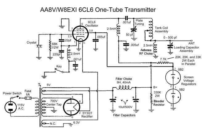
A8V W8EXI 6CL6 One Tube Transmitter. The operation of the 6CL6 transmitter is actually quite sophisticated. The A8V W8EXI 6CL6 One Tube Transmitter is a compact and efficient radio frequency (RF) transmitter that utilizes a single 6CL6 vacuum tube for...
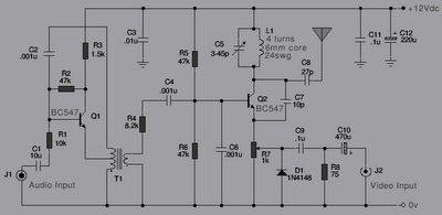
The following is a series of simple TV transmitters utilizing negative sound modulation and PAL video modulation. This design is suitable for countries employing TV systems B and G. Inductor L1 can be constructed using 24 SWG wire, consisting...
The TPTG transmitter has been transformed into a modern TNT model. This transmitter can utilize the existing K-111 power pack for both the transmitter and receiver, eliminating the need for a separate power supply unit. Building this compact transmitter...