
Valve Transmitter circuit 70W

The variable capacitors C1 and C2 will have thin sheets, and their insulations will be crafted from porcelain. Capacitor C3 operates at 2 kV. All RFCs possess an inductance of 2.5 mH and can handle a current of 100 mA. Transformer T1 features an 8K impedance primary. Insulations must be rated for a voltage of 1 kV.
Transformer T2 operates with a primary voltage of 220V and includes three secondary windings: one for 6.3V, another for 5V (supplying the 5R4), and a high voltage winding providing 2X750V at 100 mA. The 750V filter capacitors have a capacitance of 100 µF and are rated for 450V. These capacitors are connected in series, allowing them to operate at a voltage of 1200V.
At the terminals of each elementary capacitor, a 100k resistor is connected to stabilize the capacitor voltage. The supply for the isolator, oscillator, and modulator preamplifiers is derived from the mains voltage through a silicon rectifier (D), which operates at 250V and handles a current of 200 mA.
All resistors not specifically listed in the schematic are rated for 1W power. All capacitors, except those specified in the schematic, are designed to operate at voltages between 300V and 400V. Once the antenna is installed and connected to the transmitter, for optimal signal output and range, the instrument should be adjusted to indicate the minimum reading.
This transmitter design is characterized by its robust construction and high voltage capabilities, making it suitable for long-range communication applications. The use of high-quality components, such as the 6V6 and 6L6 lamps, as well as the carefully wound coils, ensures reliable performance. The inclusion of porcelain insulation and high voltage rated capacitors further enhances safety and functionality. Proper soldering of coil connections and stabilization resistors contributes to the overall integrity of the circuit, allowing for efficient signal transmission.This transmitter with a good antenna and under proper conditions of use may have a range of more than 45km. The configuration is made by the rise of the output lamp, which makes it advantageous as regards the fidelity of the emitted signal.
The 6V6 lamp is used in the oscillation step. The coil L1 will be commercially available as a 6SA7 oscillator. Intermediate reception of L1 is associated with the 6V6 cathode. In the isolation stage, the 6L6 (Buffer) lamp is used. Coil L2 consists of 40 coils of 0.3 mm thick enamelled wire wound into a 4cm diameter drum. The L3 coil, which has 60 coils of the same wire, is also wound on the same drum. The E151, high relative power lamp is used in the output stage. Coil L4 consists of 50 coils of 1.2 mm thick enamelled wire wrapped in a 5cm diameter drum. The coils of all coils must be welded.
The variable capacitors C1 and C2 will have their sheets thin Also their insulations will be made of porcelain. The capacitor C3 works at 2kV. All RFCs have an inductance of 2.5mH and can pass a current of 100mA. Transformer T1 has a 8K impedance primary. Insulations must be made for a voltage of 1kV.
Transformer T2 works with primary 220V, as secondary has three windings: A winding for 6,3V, one for 5V (supplying 5R4) and one for high voltage 2X750V, 100mA.
750V filter capacitors have a capacity of 100μF and operate at 450V. They are connected in series and operate at a voltage of 1200V.
At the ends of each elementary capacitor a resistance 100k is connected to stabilize the voltage of the capacitor. Supply of the isolator, oscillator, and modulator preamplifiers is provided by the mains voltage through a silicon rectifier (D) operating at 250V and a current of 200mA.
All resistors other than those listed in the drawing are 1W power.
All capacitors except those listed in the drawing operate at a voltage of 300-400V. Once the antenna is in place and is connected to the transmitter, for maximum signal output and range, set the instrument to indicate the minimum indication.
Related Circuits
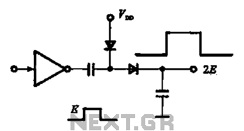
A pulse booster circuit is utilized to increase the pulse amplitude. The structure illustrated in figure (a) of the circuit can output a pulse amplitude that is twice that of the input. Figure (b) of the circuit can achieve...
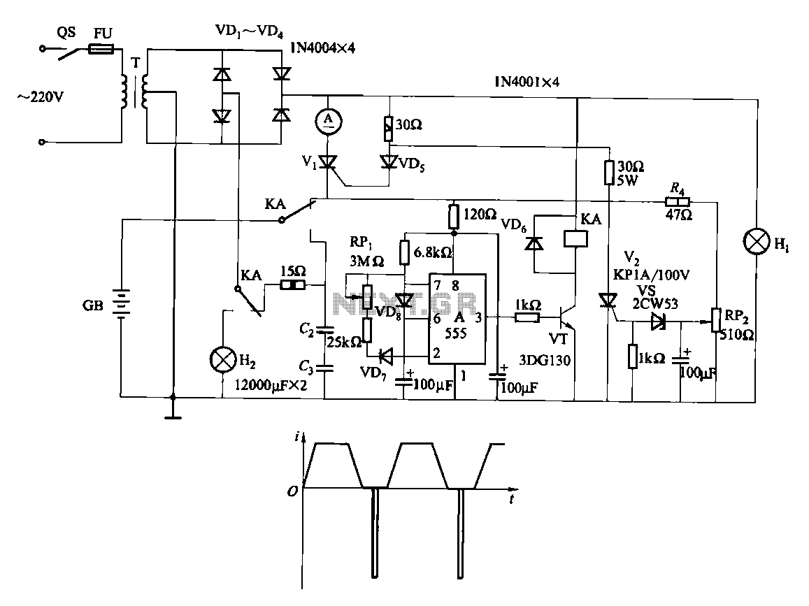
Fast and efficient charging is significantly higher than conventional charging, achieving a current charge that is ten to several times greater. When the battery voltage reaches a predetermined level (known as the polarization point), polarization within the cell becomes...
This schematic illustrates a simple yet effective LED dimmer circuit utilizing the well-known voltage regulator IC LM317T. The LM317T can function as a current regulator, as demonstrated in this circuit. It features ten super bright white LEDs, although the...
In the circuit, when E and O are input DC voltages, the motor moves to a position corresponding to the voltage. A potentiometer, coaxially connected to the motor, is used for position feedback. When the given voltage equals the...
The program utilizes the Linear LT1934 chip for the production of a high-efficiency power supply circuit design that is less demanding in terms of electrical load. It offers considerable adjustment margins. When supplied with a 24VDC input, the non-isolated...

This design outlines a tracking transmitter for audio tones operating in the FM band frequency. The circuit can function as either a signal transmitter or a remote control transmitter and utilizes only readily available components. It has a transmission...