
CDI Capacitor Discharge Ignition Circuit

The CDI ignition circuit operates by efficiently converting low voltage to high voltage for ignition purposes. The core components include a 2µF capacitor, which is charged to a high voltage of approximately 340 volts. The SCR plays a pivotal role in controlling the discharge of this capacitor, allowing for precise timing of the ignition spark. The use of a Schmitt trigger oscillator (74C14) ensures that the triggering of the SCR occurs at a consistent rate, approximately four times per second, which is suitable for many ignition applications.
The MOSFET (IRF510) is utilized to drive the low voltage side of the power transformer, which steps down the voltage from 120 volts to 12 volts, enabling the charging of the capacitor. The voltage doubler circuit on the high voltage side effectively boosts the voltage to the desired level, ensuring that the ignition coil can generate the necessary high voltage for a strong spark.
The design allows for a spark rate of up to 10 Hertz, which can be adjusted based on the application requirements. However, the limitations imposed by the transformer and oscillator duty cycle must be considered for optimal performance. The configuration of the circuit can be modified to enhance safety by grounding the negative terminal of the ignition coil, thus minimizing shock hazards.
In summary, this CDI ignition circuit is an efficient and powerful solution for generating high voltage sparks in ignition systems, with various configurations available to suit different applications while ensuring user safety.The CDI ignition circuit produces a spark from an ignition coil by discharging a capacitor across the primary of the coil. A 2uF capacitor is charged to about 340 volts and the discharge is controlled by an SCR. A Schmitt trigger oscillator (74C14) and MOSFET (IRF510) are used to drive the low voltage side of a small (120/12 volt) power transforme
r and a voltage doubler arrangement is used on the high voltage side to increase the capacitor voltage to about 340 volts. A similar Schmitt trigger oscillator is used to trigger the SCR about 4 times per second. The power supply is gated off during the discharge time so that the SCR will stop conducting and return to it`s blocking state.
The diode connected from the 3904 to pin 9 of the 74C14 causes the power supply oscillator to stop during discharge time. The circuit draws only about 200 milliamps from a 12 volt source and delivers almost twice the normal energy of a conventional ignition circuit.
High voltage from the coil is about 10KV using a 3/8 inch spark gap at normal air temperature and pressure. Spark rate can be increased to possibly 10 Hertz without losing much spark intensity, but is limited by the low frequency power transformer and duty cycle of the oscillator.
For faster spark rates, a higher frequency and lower impedance supply would be required. Note that the ignition coil is not grounded and presents a shock hazard on all of it`s terminals. Use CAUTION when operating the circuit. An alternate method of connecting the coil is to ground the (-) terminal and relocate the capacitor between the cathode of the rectifier diode and the positive coil terminal. The SCR is then placed between ground and the +340 volt side of the capacitor. This reduces the shock hazard and is the usual configuration in automotive applications. 🔗 External reference
Related Circuits
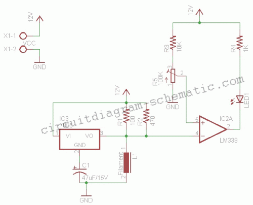
This circuit is a simple air flow detector that signals the presence of air flow. The sensor utilized is a filament incandescent lamp. Components include an air flow detector, a sensor, an LED, and an LM339 operational amplifier. The air...
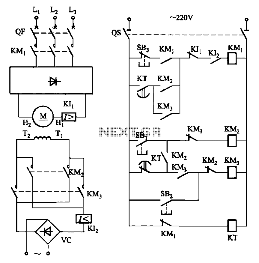
The circuit depicted in Figure 3-193 illustrates a separately excited DC motor. The brake circuit is not activated; therefore, positive reversals occur alternately using a delay action relay, ensuring that the motor reverses direction after coming to a stop. The...
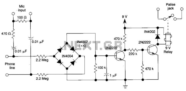
The DC voltage on a telephone line typically ranges from 45 to 50 V when on-hook and drops to around 6 V when off-hook. This circuit utilizes the voltage drop to activate a relay, which in turn controls a...
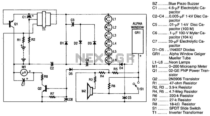
Q1 is a PNP power transistor used in conjunction with a ferrite transformer to form a blocking-type oscillator. This oscillator operates at a fixed frequency, with feedback for sustaining oscillations provided by capacitor C1. Due to the turns ratio...
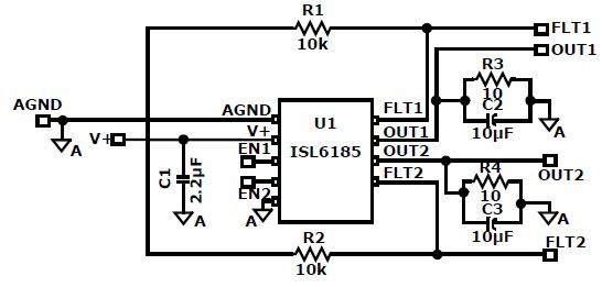
The ISL6185 USB power controller family can be utilized to design a straightforward USB power supply electronic project that offers fully independent overcurrent (OC) fault protection for two or more USB ports. This product family includes sixteen distinct functional...
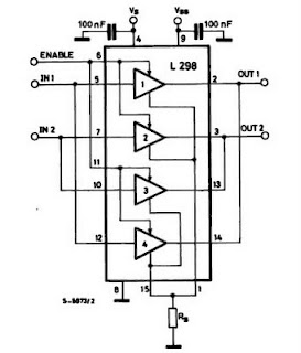
The IC H-Bridge DC motor driver L298 contains two H-Bridge circuits, allowing it to drive two DC motors simultaneously. Each H-Bridge circuit can deliver currents up to 2A. When used in parallel, the L298 can provide a total current...