
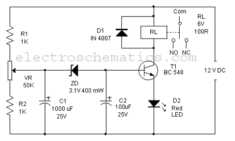
Electric sewing machine saving circuit

The electric sewing machine saving circuit operates through a combination of a Hall effect sensor and a relay mechanism to enhance energy efficiency and user safety. The Hall switch IC detects the presence of a magnetic field generated by the foot pedal's magnet. When the circuit is powered, the resistor (R) and capacitor (Ci) form an RC network that ensures stable operation of the relay and prevents voltage spikes.
The silicon rectifier bridge (UR) converts the alternating current (AC) from the power source into direct current (DC), which is then smoothed by the filter (G). The voltage regulator IC ensures that the output voltage remains stable at 12V DC, which is essential for the proper functioning of the sewing machine's electronic components.
In the idle state, when the operator is not pressing the foot pedal, the Hall switch IC detects the magnetic field, causing the relay (K) to remain energized. This action opens the normally closed contact, effectively cutting off power to the sewing machine and illuminating the red LED as an indicator that the machine is not operational.
When the operator engages the foot pedal, the magnetic clutch lever (FI1) is activated, disrupting the magnetic field detected by the Hall switch IC. This loss of magnetic field causes the relay (K) to de-energize, closing the normally closed contact, which allows current to flow to the sewing machine. The LED indicator turns off, signaling that the machine is now powered and ready for operation.
This circuit design is particularly beneficial in preventing accidental activation of the sewing machine when it is not in use, thereby enhancing safety and reducing energy consumption. The integration of the Hall effect sensor with the relay mechanism allows for a responsive and reliable control system, ensuring that the sewing machine operates only when intended.Electric sewing machine saving circuit as shown, line the main elements by the Hall switch IC IC and relay K composition. Closing switch os, power-on, after R, and Ci RC Buck, UR rectifier bridge silicon, G filter, vs the regulator, IC to provide the 12V DC power supply e when the operator does not move the sewing machine foot pedal magnet in the operating position corresponding to the IC. K pull power, open the normally closed contact, seam sewing machine is not powered. Red light-emitting diode (LED) lights. On the other hand, stepped on a sewing machine, FI1 attached to the fixed magnetic clutch lever on the machine l of iron down.
IC lose magnetic field, which was feet high potential, K loss of power release, the main circuit normally closed contacts reset, M running, LED is off.
Related Circuits
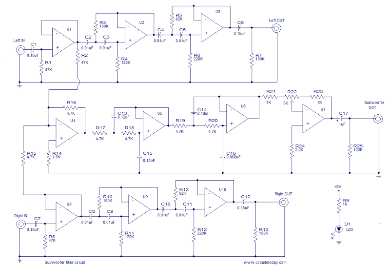
This is the schematic diagram of an operational amplifier (op-amp) based subwoofer filter. Audio frequencies below 200 Hz are typically categorized within the subwoofer range, indicating that a subwoofer filter should have a cutoff frequency around 200 Hz. The...
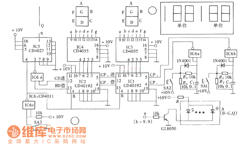
The game-scoring display screen circuit diagram is depicted in the image above. The circuit consists of an add/subtract scoring input circuit, an add/subtract scoring circuit, a counting-decoding display circuit, and a reset circuit. The game-scoring display circuit is designed to...
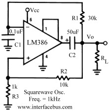
Several operational amplifier circuits are presented here, configured as square wave oscillators. A square wave is a periodic pulse train with a 50 percent duty cycle. The operational amplifier functions as a high-gain amplifier, and oscillation is achieved with...
Protect your LCD or Plasma TV with this small delay-on circuit. The SMPS-based power supply of these modern electronic devices is susceptible to voltage spikes. This delay-on circuit is designed to enhance the protection of LCD and Plasma TVs by...
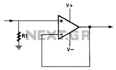
An operational amplifier (op amp) can function as a unity gain amplifier by connecting its output to its inverting input as illustrated. The load resistance (Rl) should be sufficiently low to prevent the op amp's bias current from introducing...
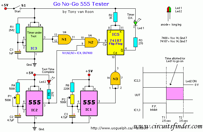
This circuit illustrates a Go-No/Go Tester Circuit utilizing a 555 Timer IC. Features include a more advanced unit with a precise timed testing procedure. The Go-No/Go Tester Circuit is designed to evaluate components or assemblies by providing a simple pass/fail...