
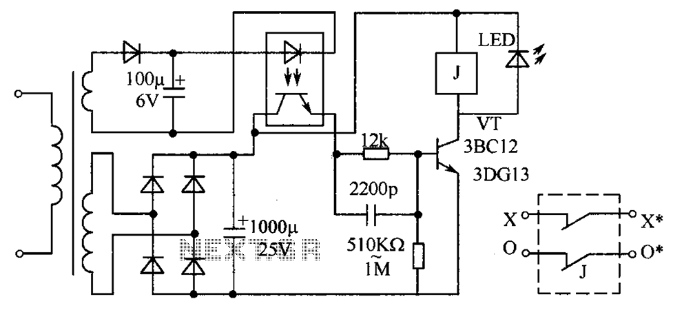
Photo interrupter circuit diagram

The described circuit operates on a principle of light sensitivity and feedback control. Initially, in the dark state, the electromagnet M is energized, allowing a current to flow that keeps the system in a ready state. The phototransistor acts as a light sensor; when illuminated, it activates, which subsequently deactivates the final stage transistor. This deactivation results in the solenoid being released, indicating a change in the circuit state from active to inactive.
The inclusion of a 1M ohm feedback resistor plays a crucial role in maintaining the transistor’s state. This feedback mechanism allows the circuit to retain its activated state even after the light source is removed. The time-sensitive nature of the transistor is critical for ensuring that the circuit remains responsive to transient changes in light conditions.
The reset mechanism is straightforward; pressing the reset button T reverts the circuit back to its original state, allowing for repeated operation. This functionality is essential for applications where the circuit needs to be reset frequently without manual intervention in the light detection process.
Furthermore, the option to use a Darlington transistor as an amplifier enhances the circuit's performance by providing a higher current gain. This characteristic is particularly beneficial in applications requiring substantial amplification of the input signal from the phototransistor, thereby improving overall sensitivity and responsiveness of the circuit.
Overall, this circuit design effectively integrates phototransistor operation, feedback mechanisms, and amplification to create a versatile system suitable for various electronic applications. Circuit at rest (dark) state operation the electromagnet M current flows, once there is sufficient strength so that light shines on the phototransistor is turned on, that is th e final stage transistor is in the OFF state, the solenoid release. Because by 1M ohm feedback to the photosensitive base of the transistor effect, so that even light cancel time-sensitive transistor is still turned on. Until press the reset button T, in order to return to the initial state. Darlington transistor which can be used in place of an amplifier greater magnification.
Related Circuits

This circuit is designed to drive an ultrasonic transducer. A question has arisen regarding how to limit the output current, as a 60W transducer may be at risk of damage due to excessive current. Guidance or examples for integrating...
The circuit protection mechanism utilizes optocouplers for on-off control. Under normal voltage conditions, the output from the optocouplers is minimal, and the VT transistor operates in reverse bias. However, if the circuit voltage increases due to reasons such as...
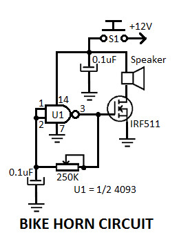
This simple electronic bicycle horn circuit utilizes a single gate from a 4093 quad 2-input NAND Schmitt trigger (U1) connected in a straightforward, low-frequency square wave configuration. The electronic bicycle horn circuit operates by generating a square wave signal that...

This is a design circuit for an alarm. This circuit is intended for an anti-theft wireless alarm that can be used with any vehicle operating on a 6 to 12 volt DC supply system. A mini VHF FM radio-controlled...

Figure 283 illustrates a blackout emergency lighting controller designed for straightforward external installation with two leads. This controller can directly replace the P Chan Tong Ge opening. Under normal power conditions, it functions like a conventional switch to control...
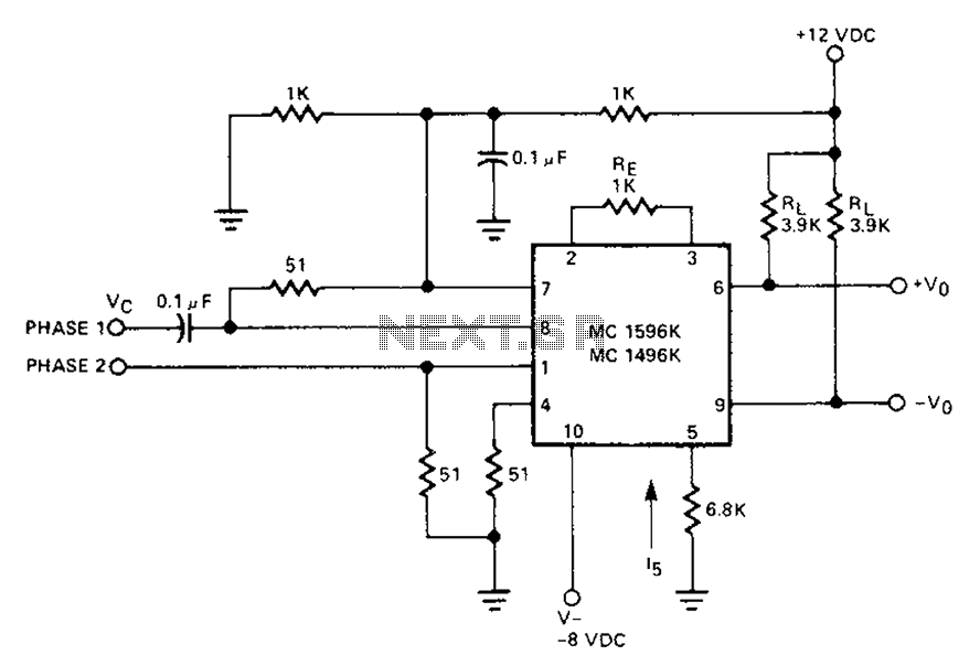
The circuit involves a Signetic balance modem connection utilizing a transistor array as a phase detector. It provides information about the cosine of the phase angle, which corresponds to the frequency of the input signal combined with the integrated...