
3 Band graphic equalizer circuit

The three-band graphic equalizer circuit utilizes the LF351 op-amp, which is known for its low noise and high performance, making it suitable for audio applications. The circuit is designed to modify audio signals by selectively boosting or attenuating specific frequency ranges, enhancing the overall sound quality.
In this configuration, the op-amp is set up in an inverting amplifier arrangement, which allows for phase inversion and gain control. The gain of the circuit is determined by the feedback network formed by the resistors and the potentiometers. Each potentiometer (R3 for low frequencies, R6 for mid frequencies, and R9 for high frequencies) is connected to the inverting input of the op-amp, allowing the user to adjust the gain for each frequency band independently.
The input audio signal is fed into the circuit, where it first passes through a coupling capacitor to block any DC offset. The signal is then routed to the inverting input of the op-amp. The output of the op-amp is connected back to the inverting input through a feedback resistor, which, along with the potentiometers, sets the gain for each frequency band. The non-inverting input is typically grounded in this configuration.
The selected frequency ranges are achieved through the careful selection of resistor and capacitor values in conjunction with the potentiometers. The circuit can be fine-tuned to provide a flat frequency response or to emphasize certain frequencies, depending on the application requirements.
Overall, this simple yet effective equalizer circuit can be easily constructed and modified, making it an excellent choice for audio enthusiasts looking to enhance their sound systems with a customizable frequency response.Here is a simple 3 band graphic equalizer circuit made of a single op amp IC LF351 (IC1) and few passive components. The component values of this circuit are not very critical and can be replaced with nearest values with a little loss on the performance.
This feature make it easy to be assembled from your junk box. The opamp LF351 is wired to operat e in three frequency ranges- high, medium and low. The circuit is designed such that the circuit produces +/-20 dB boost or attenuation for 50Hz, 1KHz and 10Khz by varying POT`s R3, R6 and R9. The maximum amplification for any of these bands at maximum supply voltage is 20dB. The opamp LF 351 is wired as an inverting amplifier whose response to frequencies 50Hz, 1Khz and 10KHz can be varied by adjusting POT`s R3, R6 and R9.
🔗 External reference
Related Circuits
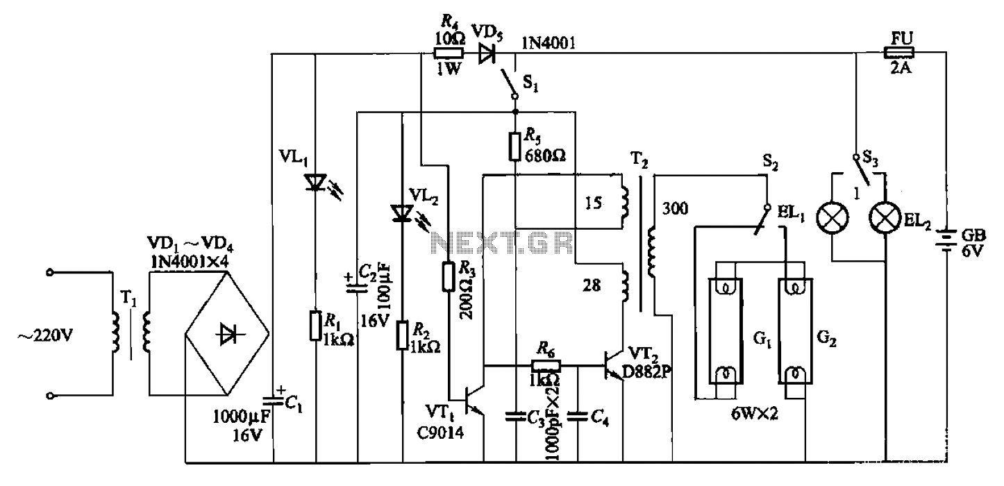
The 786A multi-functional double-tube fluorescent emergency circuit is illustrated in Figure 2-129. This circuit shares similarities with Figure 2-125. The 786A multi-functional double-tube fluorescent emergency circuit is designed to provide illumination during power outages or emergencies. It utilizes two fluorescent...
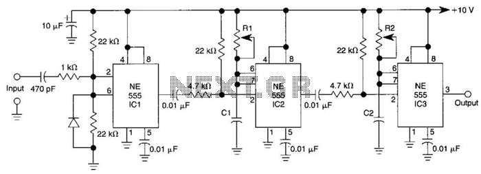
Three 555 IC timers are utilized in this circuit to create a simple delayed-pulse generator. IC1 functions as a waveform shaper to generate a rectangular waveform. IC2 generates a delaying pulse that triggers IC3 on the trailing edge of...
The simplest polarity protection technique is to connect a series diode to the power line input. The diode conducts only when the power supply is connected correctly. A series diode is an effective method for preventing reverse polarity in electronic...

This design outlines a power supply circuit capable of producing a 5V source voltage. The circuit is constructed using TTL integrated circuits (ICs) and features a simple design. In circuits utilizing TTL ICs, the supply voltage is critical, as...
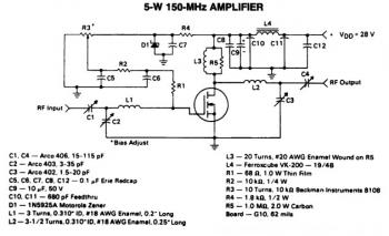
This is a 5W -150MHz RF amplifier circuit that utilizes the MRF123 TMOSFET. The MRF123 is a high-gain FET which may exhibit instability at both VHF and UHF frequencies; therefore, a 68 Ohm input loading resistor is employed to...
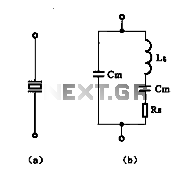
The crystal equivalent RLC circuit is illustrated. The RLC circuit can operate in either a series resonant or parallel resonant configuration. The crystal equivalent RLC circuit is a fundamental electronic circuit that models the behavior of a crystal oscillator. This...