
Cheap surround sound system circuit diagram

The circuit employs the LM1458 dual operational amplifier to effectively manage audio signals for enhanced surround sound experience. The left audio input is processed through a coupling network comprising C2 and R1, directing the signal to the non-inverting input of the first op-amp. The right audio input follows a similar path, routed through R4 and C2 to the non-inverting input of the second op-amp. The configuration allows the circuit to amplify the differential audio signals, which is essential for creating a surround sound effect that enhances the listening experience.
The outputs from both op-amps are connected to a summation point, enabling the circuit to derive the difference between the left and right signals. The variable resistors, VR1/1 and VR1/2, are critical for adjusting the gain of each channel, allowing for precise control over the audio levels. This feature is particularly useful in environments where sound balance between channels is crucial.
The coupling capacitors C3 and C4 serve to block any DC offset and ensure that only the AC audio signals pass through to the output stage. This improves the overall sound quality and prevents any potential damage to connected audio equipment. The output stage is designed to interface with either headphones or a larger amplifier, making the circuit versatile for various audio applications.
The switch S1 provides the user with the option to select between different audio output configurations, allowing for flexibility in routing audio to surround speakers or maintaining a standard left-right output. Capacitors C1 and C2 are integral in introducing a delay to the audio signal, which can be adjusted using VR1. This delay feature can enhance the spatial perception of sound, allowing users to tailor the audio experience to their preferences. Overall, the design demonstrates a thoughtful approach to audio signal processing, ensuring high-quality sound reproduction with adjustable parameters for user customization.Using the LM1458 IC number to expand the difference of the input signal left (L). It came out as surround sound sure enough. When raising the power and enter the left and right input circuit. The signal on the left (L) to signal coupling through C2 and R1 to enter the pin 5 of IC1 / 1. And signs on the right (R) to signal coupling through R4 to C2 and to the pin 3 of IC1 / 2. Then the amplifier IC1 is the difference. Which the same signal is lost. Balance, but only signals different from the output pin 7 and pin 1. The VR1 / 1 and VR1 / 2 is a control gain of the signal on each side. Then the signal via C3 and C4 are coupling the audio signal and send out better, The output. By the way this output is connected to the headset. Or will be connected to the amplifier at all. When the switch S1 to select a location signal. The audio will pass to the surround speakers and left and right. The C1 and C2 act to slow down the audio delay. Than normal. Forward and adjust VR1 to delay the sound is very slow. Little or slow as desired. 🔗 External reference
Related Circuits
This circuit is designed for accurate time-base generation utilizing the commonly available 3.5795 MHz crystal, which is frequently used in telecommunication equipment. A crystal-based oscillator combined with a divider IC chain or a similar circuit, such as an ASIC,...
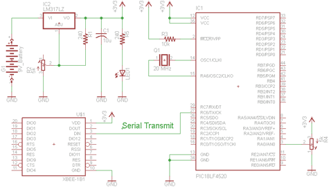
There are two schematics to examine for constructing a transmitter/receiver system. The first schematic is the transmitter, featuring a variable trimpot connected to RA0. The trimpot's value will be transmitted from the Tx pin of the PIC to the...
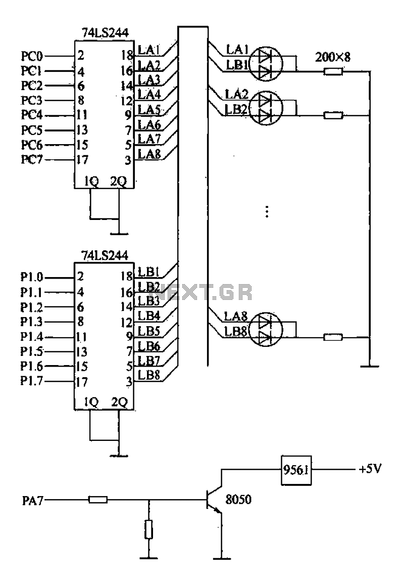
Alarm interface circuitry featuring a two-color light-emitting diode (LED) display. When LAi is at a high level and LBi is low, the green LED lights up; conversely, if LAi is low and LBi is high, the red LED lights...
Aux Send is an in-studio performance web show and podcast dedicated to showcasing unique, diverse, and talented independent musicians. Aux Send serves as a platform for independent musicians, providing them with an opportunity to perform and share their artistry in...
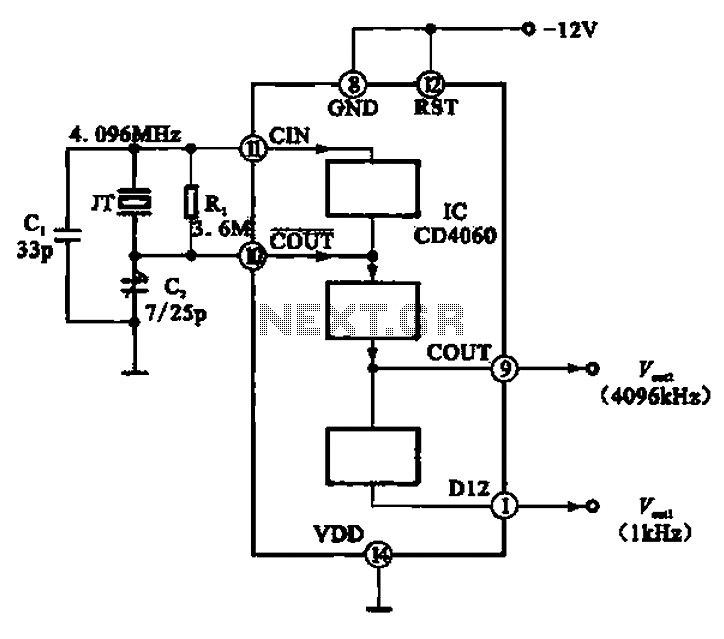
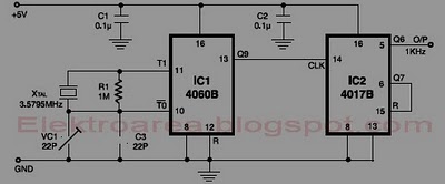
A 1 kHz square wave signal source circuit is illustrated using the CD4060 integrated circuit. The CD4060 operates with an external crystal oscillator and compensating capacitors such as C1 and C2. The internal oscillator circuit of the chip is...
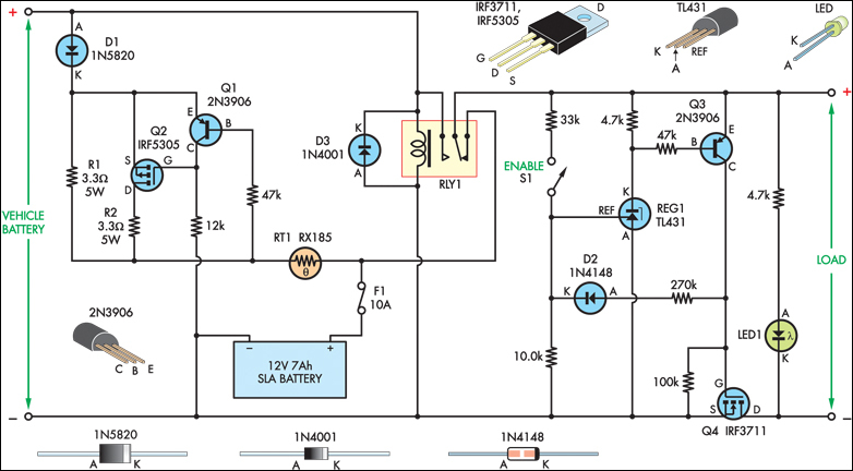
The SLA battery is charged from the vehicle's battery. When the engine is running, the voltage remains fairly constant, which greatly simplifies the charging circuit. If the SLA battery is fully charged, any further charging current from the vehicle...