
in car charger and switcher circuit for sla battery

The described circuit is a battery charging system designed for Sealed Lead Acid (SLA) batteries, utilizing the vehicle's battery as the power source. The operation of the circuit hinges on the vehicle's alternator maintaining a stable voltage output while the engine is running, typically around 13.8V to 14.4V. This stable voltage is crucial for ensuring efficient charging and simplifies the design of the charging circuit.
The circuit features a resistor (R1) rated at 3.3W to 5W, which serves as a current limiting component. When the SLA battery reaches a full charge, the current from the vehicle's battery is restricted by this resistor, preventing overcharging and potential damage to the SLA battery.
In scenarios where the SLA battery is deeply discharged, the voltage across R1 will decrease sufficiently to turn on the PNP transistor (Q1). This transistor plays a pivotal role in activating the charging process. When Q1 is biased on, it allows current to flow to the P-channel MOSFET (Q2). The MOSFET, once turned on, facilitates additional charging current to the SLA battery through another resistor (R2), effectively creating a two-step charging process.
This two-step charging mechanism is beneficial as it allows for an initial bulk charging phase when the battery is low, followed by a trickle charge as the battery approaches full capacity. This method not only enhances the efficiency of the charging process but also prolongs the life of the SLA battery by preventing overcharging and excessive heat generation.
Overall, the design ensures that the SLA battery is charged safely and effectively while utilizing components that are readily available and cost-effective, making it suitable for automotive applications.The SLA battery is charged from the vehicle s battery. When the engine is running, the voltage remains fairly constant, which greatly simplifies the charging circuit. If the SLA battery is fully charged, any further charging current from the vehicle battery is limited by a 3.3W 5W resistor (R1).
If the SLA battery is deeply discharged, the voltage drop across this resistor will be enough to bias on PNP transistor Q1. This will turn on P-channel Mosfet Q2 and it will provide further charging current via R2, effectively becoming a 2-step charger..
🔗 External reference
Related Circuits
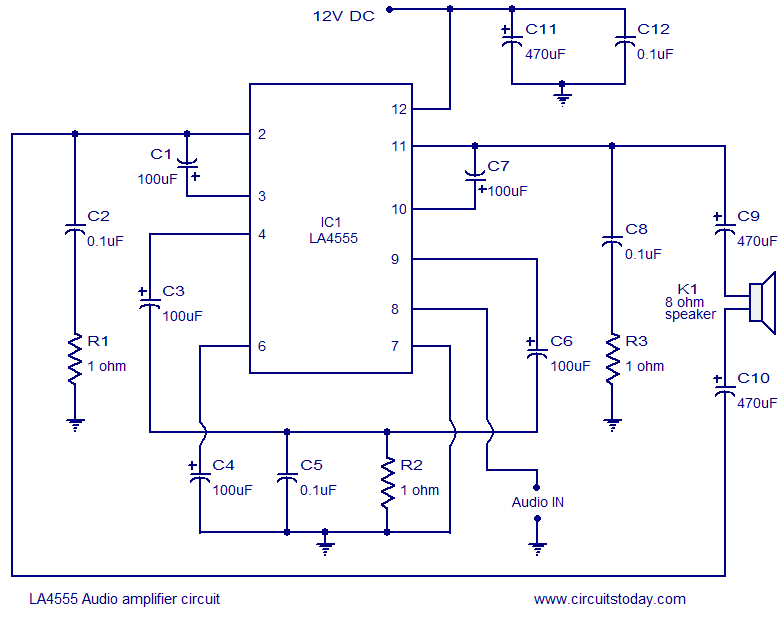
The LA4550 audio amplifier operates in a BTL (Bridge-Tied Load) configuration. This amplifier is capable of delivering 4W into an 8-ohm load when powered by a 12V power supply. The LA4550 is designed for audio amplification applications, particularly in situations...

This sensor switch circuit features nine channels and consists of three integrated circuits along with several resistors. The 74HC147, which has a high input impedance, enables the use of 4.7 MΩ resistors to establish a logic level "high" for...

This circuit is designed for a UHF TV antenna and provides a 15 dB preamplification. It is constructed using a transistor and minimal components. The schematic features the BF180 UHF transistor. The first stage consists of a band-pass filter...
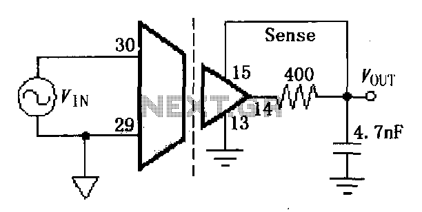
The ISO107 ripple reduction circuit includes an RC high-pass filter at the output to filter the output voltage ripple without impacting the DC characteristics. This configuration allows for a reduction of the 800kHz ripple voltage to less than 3mVp-p. The...
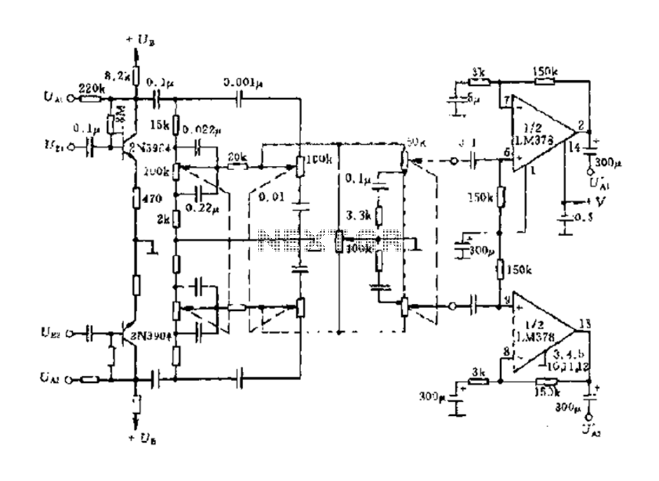
The dual-channel circuit features the LM378 dual operational amplifier and operates with a supply voltage of 24V, supporting an 8-ohm load (or 16 ohms). Each channel delivers an output power of 4W. The circuit includes internal current limiting and...
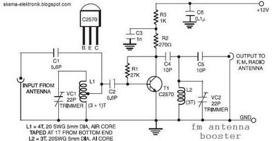
The coil L2 is tapped at the first turn from the ground lead side and is similar to coil L1, but consists of only three turns. The pin configuration of the transistor 2SC2570 is illustrated in the FM antenna...