
circuit 9 second countdown power on

The described circuit comprises a 555 timer configured in astable mode to generate a clock signal with a frequency of approximately 1 Hz. This clock signal is utilized to decrement a binary counter, typically a 74HC4040 or similar, which counts down from a preset value (in this case, 9). The counter output is monitored, specifically the carry-out signal at pin 7, which indicates when the counter has reached zero.
When the switch is opened, the timer begins its operation, producing a pulse every second. Each pulse causes the counter to decrement its value until it reaches zero. At this point, the carry-out signal transitions to a low state, which activates a relay. The relay operates at 12 volts and is often used to control higher power loads, providing isolation between the low voltage control circuit and the high voltage output.
The output from the relay can be used to control various devices or indicators. The circuit is designed to stop the timer when the carry-out signal goes low, achieved through a low signal applied to the reset pin (pin 4) of the timer. This effectively halts the clock signal generation, preventing further counting.
The relay remains energized until the switch is closed again, which serves as a manual reset mechanism for the counter. Closing the switch sends a high signal to the reset input of the counter, returning it to its initial state (count of 9). Additionally, the duration of the clock signal can be fine-tuned by adjusting the resistor connected to pin 3 of the 555 timer. This allows for flexibility in timing applications, accommodating different requirements for the timing interval.
This circuit can be employed in various applications, including timers for automatic systems, delay circuits, or any scenario where a timed output is required. Proper selection of components and values will ensure reliable operation and desired performance characteristics.When the switch is opened, the timer produces an approximate 1 second clock signal, decrementing the counter until the 0 count is reached. When the zero count is reached, the `carry out` signal at pin 7 of the counter moves low, energizing the 12 volt relay and stopping the clock with a low signal on the reset line (pin 4).
The relay will remain e nergized until the switch is again closed, resetting the counter to 9. The 1 second clock signal from the 555 timer can be adjusted slightly longer or shorter by increasing or decreasing the resistor value at pin 3 of the timer. 🔗 External reference
Related Circuits
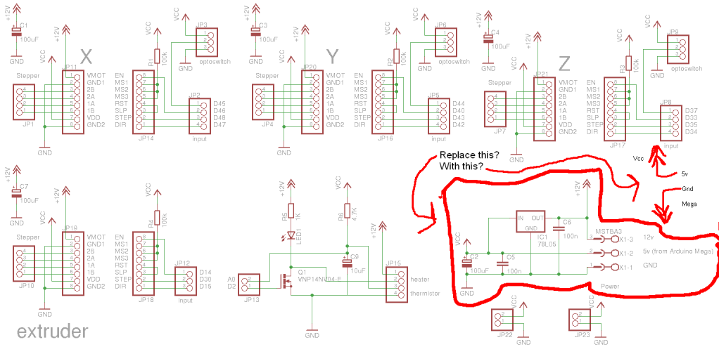
Preparing to assemble Adrian's Pololu stepper driver circuit has raised a question. He indicates that if using 5V from the Arduino Mega, the 78L05 voltage regulator should be omitted. This is a positive development, although there is an incorrect...
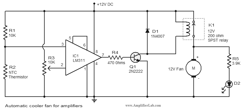
An automatic cooler fan for amplifiers is a circuit designed to conserve power in amplifier circuits. This circuit activates the fan. The automatic cooler fan circuit for amplifiers operates by utilizing temperature sensors to monitor the heat generated by the...
In the silicon-controlled trigger circuit, a cadmium sulfide cell is connected to a relaxation oscillator, which serves as a sensor to activate a blinking light in a darkroom. This setup causes a speaker to emit a warning sound of...
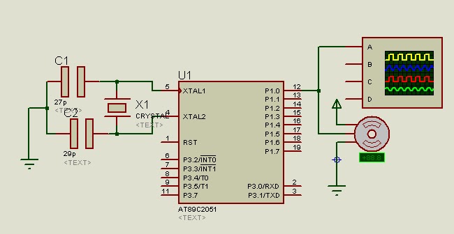
A program is available to control a simple servo motor in both directions. This program has been tested and can be shared for others to benefit from it. It allows the servo motor to rotate in both clockwise and...
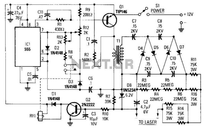
IC1 is a 555 timer operating at approximately 16 kHz. This integrated circuit drives Q1, a TIP146 transistor, which generates a 12-V square wave across the primary winding of transformer T1. This results in an output voltage ranging from...
70 W switching power supply utilizing the KA2S0880 integrated circuit. Refer to the specified page for an explanation of the associated circuit diagram. The 70 W switching power supply designed with the KA2S0880 integrated circuit (IC) is a versatile solution...