
Pololu Circuit

Sebastien notes that nearly all suppliers are shipping from the US or have minimum order requirements. Arrow appears to ship small quantities from the US but has a lead time of 12 weeks. An email has been sent to clarify whether this lead time applies to all orders or only large ones. Efforts will continue to find an alternative part while awaiting a response from Arrow.
The Pololu stepper driver circuit is designed to control stepper motors efficiently, utilizing an Arduino Mega as the primary microcontroller. The circuit typically includes a voltage regulator, such as the 78L05, to provide a stable 5V supply; however, when directly powered from the Arduino, this component can be omitted. The schematic should be carefully analyzed to ensure proper connections, particularly regarding the ground symbol, which must be accurate to prevent potential issues in operation.
Capacitors play a crucial role in stabilizing the power supply to the stepper drivers. The use of a 100uF electrolytic capacitor is advisable for dampening voltage spikes during motor operation, while a 1uF ceramic capacitor is effective for filtering out high-frequency noise. This combination is essential for maintaining reliable performance, especially in applications where precision is critical.
The circuit's power requirements indicate that a 12V supply is necessary for both the steppers and the extruder heater. It is important to ensure that this voltage is supplied correctly from the designated connector, which may require verification to avoid operational issues.
In summary, the assembly of the Pololu stepper driver circuit involves careful consideration of component selection and circuit design to ensure reliable performance. The integration of adequate capacitors, accurate voltage supply, and attention to schematic details will contribute to the successful operation of the stepper motors and associated components.Getting ready to put Adrian`s Pololu stepper driver circuit together and have run into a question. He mentions that if you are using 5v from the Arduino Mega, to leave out the 78L05. Great! I am thrilled to only have the wrong symbol for ground. I have just enough electronics knowledge to read a schematic and fumble through getting it togethe r. I think I can handle this one (fingers crossed). Thanks for the help. If I run into issues do you mind me asking advice of you. It`s nice to have a contact with roughly the same setup. I would also consider keeping the two capacitors there to minimize voltage spikes when the Polulu`s switch on and off. Run and already regulated 5 volts from another card over ribbon cable leaves it very "soft" and unable to instantly supply large inrush currents, or absorb back EMF when motors are turned off.
Keeping the 100uF electrolytic to handle big, long duration impulses and the 1uF ceramic to short out the high frequency spikes and noise may help make the board more reliable, fewer missed or extra steps. EDIT: After looking closer at the whole circuit, I see that there are already 100uF electrolytic caps for each Polulu.
And looking closely at the internal schematic for the Polulu`s, they have their own internal 0. 1uF surface mount capacitors, so no need for any extras beyond what is still in the schematic after the 7805 and attached parts are removed. I am a little confused after looking even closer at the circuit. It looks like the only source of the 12 volts needed to drive the steppers and the extruder heater came from the connector that is now labeled 5V, Mega, Gnd.
Should this still be: Sebastien- All but one supplier is shipping out of the US or has minimum orders. It looks like Arrow ships small amounts from in the US but shows a 12 week lead time. I`ve e-mailed them to see if that lead time is for all orders or just for large orders. Hopefully the lead time is only for large quantities. I`m also going to keep looking for an alternate part while I`m waiting hear back from Arrow. 🔗 External reference
Related Circuits
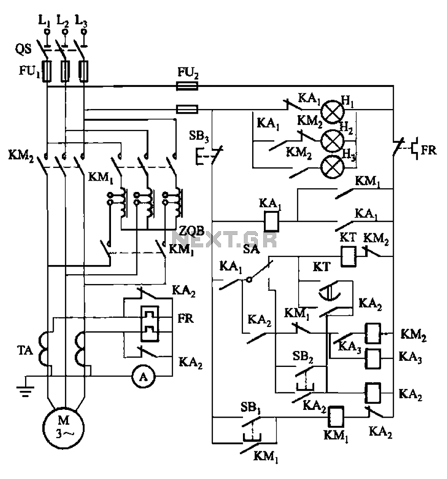
The circuit illustrated in Figure 3-56 features both manual and automatic start-up modes. It incorporates two relays, KA2 and KA3, within the control loop. The circuit design ensures that KM1 is cut off before and after activating KM2. A...
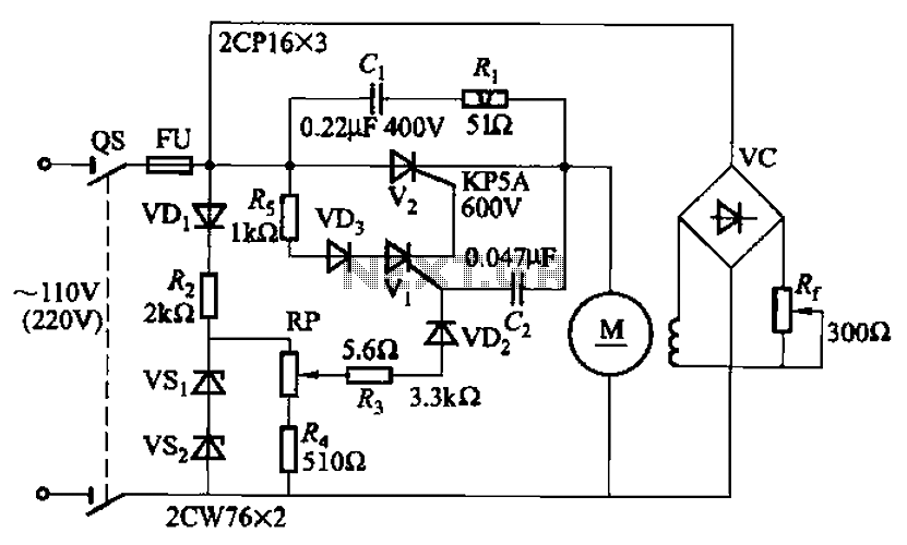
A 100W resistance-triggered motor control circuit designed for arc welding machines. It features an adjustment potentiometer (Rr) that can modify the DC motor excitation current. Additionally, a regulator (RP) is included to adjust the DC motor armature voltage, enabling...
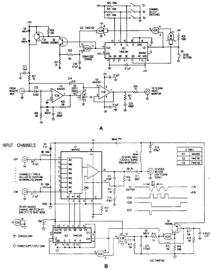
In the video system shown in Figs. A and R, a single coaxial cable transmits power to a remote location, selects one of eight video channels, and returns the chosen signal. This system can select from multiple remote surveillance...
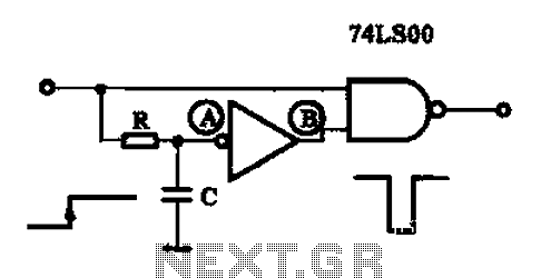
A single pulse signal generating circuit is designed to produce a one-shot pulse output. This circuit can be utilized in applications requiring a digital reset signal or to halt a signal. It operates as a non-synchronous differential circuit. The single...
This signal generator is designed for the realignment of radio receivers. The unit is inexpensive and relatively simple but adequately serves its intended purpose. However, the output is not a pure sine wave, which may make it unsuitable for...
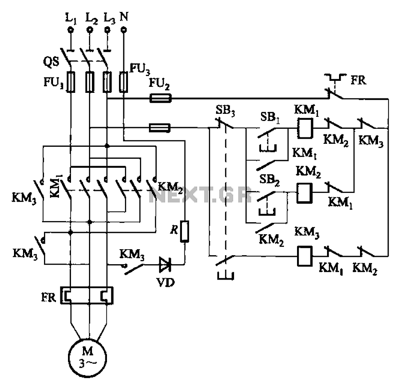
The circuit illustrated in Figure 3-145 employs a rectifier diode brake for neutral grounding in a three-phase, four-wire power supply system. This circuit design incorporates a rectifier diode brake, which plays a crucial role in ensuring the safety and reliability of...