
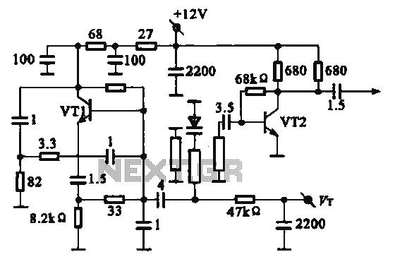
One Transistor FM Receiver circuit diagram

The FM receiver circuit primarily consists of a single transistor functioning as the active amplification element. The simplicity of this design allows for easy construction and understanding of fundamental FM reception principles. The circuit typically includes a few passive components such as resistors, capacitors, and an inductor, which together form the necessary tuned circuit for signal reception.
In operation, the circuit receives FM signals through an antenna, which can be a simple wire. The antenna picks up radio frequency signals, which are then filtered and amplified by the transistor. The transistor is configured in a common-emitter or common-collector arrangement, depending on the desired output characteristics.
The output from the transistor is typically at a low level, suitable for direct connection to earphones. For applications requiring a louder output, such as driving a loudspeaker, an additional amplifier stage is necessary. This amplifier can be constructed using another transistor or an integrated circuit designed for audio amplification.
To enhance performance, the circuit may include additional components such as a variable capacitor for fine-tuning the frequency response, allowing the user to select different FM stations. Furthermore, bypass capacitors may be employed to stabilize the power supply and improve audio quality by reducing noise.
Overall, this simple FM receiver circuit serves as an excellent introduction to radio frequency electronics, demonstrating essential concepts such as signal amplification, tuning, and audio output interfacing.This is a very simple FM receiver which build based on one transistor only. No chip or another active component. The output is connected to earphones, you need an amplifier circuit if you want to listen the radio with a loudspeaker. 🔗 External reference
Related Circuits
The local oscillator operates at frequencies of 1 GHz or higher, utilizing a common collector circuit, which makes it challenging to generate low-frequency self-oscillation. Typically, the local oscillator signal is passed through a buffer amplifier stage before being applied...
Gates U1-a and U1-b of the 4093 quad 2-input NAND Schmitt trigger are connected in variable, low-frequency square-wave oscillator circuits. The output of gate U1-a is connected to one of the inputs of gate U1-b. The square-wave output of...
The back EMF voltage spikes produced by stepper motors, especially higher voltage motors, can damage a PC's printer port if connections are made incorrectly, flyback diodes are absent, or connected in reverse. The safest options are opto-isolated or buffered/inverted...

A static device that couples two circuits to transfer alternating current (AC) from one circuit to another through electromagnetic induction. The current maintains the same frequency but may vary in voltage, phase, or impedance values. A transformer consists of...
The L29 Stepper Motor Controller IC facilitates the control of four drive signals for two bipolar and four unipolar footfall motors in a microcomputer-controlled appliance. It allows for motor operation in half-step, full-step, and wave drive modes, utilizing switch-mode...

The thermostat electric circuit operates as depicted in the figure. It has three settings: off, low power (Lo), and high power (Peru HL). When the DIP switch SA is set to the Lo position, 220V AC is directed through...