
27MHz crystal oscillator transmitter simulation in PSPICE

The 27 MHz transmitter circuit typically consists of several key components, including an oscillator, modulator, amplifier, and antenna. The oscillator generates a radio frequency signal at 27 MHz, which serves as the carrier wave for transmission. Commonly, a crystal oscillator or a phase-locked loop (PLL) circuit is employed to achieve stable frequency generation.
The modulator is responsible for encoding the information signal onto the carrier wave. This can be accomplished through amplitude modulation (AM), frequency modulation (FM), or phase modulation (PM), depending on the application requirements. The choice of modulation technique will influence the design of the modulator circuit, which may involve components such as operational amplifiers, diodes, and filters to shape the signal appropriately.
Following modulation, the signal is fed into a power amplifier, which increases the power level of the signal to ensure adequate transmission range. The amplifier circuit design should account for factors such as gain, linearity, and efficiency to maintain signal integrity while minimizing distortion.
Finally, the antenna is a critical component that converts the electrical signal into electromagnetic waves for transmission through the air. The design of the antenna, whether it be a dipole, monopole, or another type, should be matched to the transmitter's output impedance for optimal performance.
In PSPICE, the simulation can be set up by creating a schematic that incorporates these components. Each part of the circuit can be represented using appropriate models, and the simulation parameters can be adjusted to analyze the circuit's behavior under various conditions. The output can be visualized through waveform analysis, allowing for the evaluation of key performance metrics such as frequency stability, modulation fidelity, and transmission range.
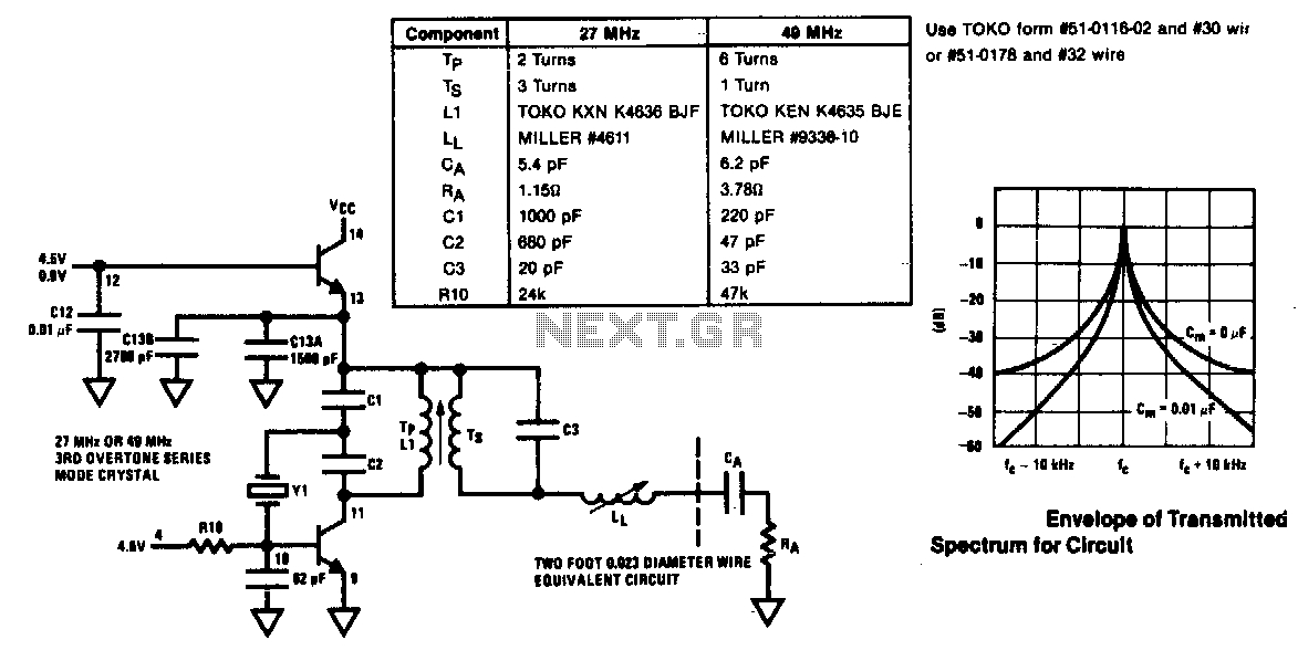
By simulating the 27 MHz transmitter circuit in PSPICE, it is possible to identify potential issues and optimize the design before physical implementation, ensuring a more efficient and effective transmitter system.I want to simulate 27MHz transmitter circuit in PSPICE. Circuit diagram is given as Figure-1 in following.. 🔗 External reference
Related Circuits
In 1896, Marconi successfully transmitted electromagnetic waves over a distance of approximately 3 kilometers. Shortly thereafter, he established radio communication across water between Lavernock Point in South Wales and Flat Holm Island. The transmitter utilized a spark inductor connected...
The voltage Vc1 increases linearly when the pull-up resistor RA in the monostable circuit is replaced with a constant current source, resulting in a linear ramp. The circuit for generating the linear ramp and the corresponding waveforms are illustrated...
The modulator and oscillator comprise two NPN transistors. The base of the modulator transistor is powered by a bidirectional current source, with the voltage range for the high condition restricted by a saturating PNP collector connected to the pin...
The circuit is a radio frequency (RF) oscillator that operates around 100 MHz. Audio signals captured and amplified by the electret microphone are sent to an audio amplifier stage constructed around the first transistor. The output from the collector...
The transmitter described here includes an additional RF power amplifier stage following the oscillator stage, which increases the output power to 200-250 milliwatts. When connected to a properly matched 50-ohm ground plane antenna or a multi-element Yagi antenna, this...
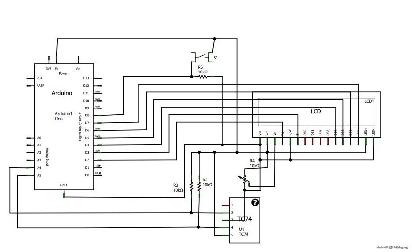
A tutorial on LCD communication was planned for a later date due to high demand. A circuit was already assembled for testing a new LCD provided by element14. The tutorial explains how communication functions with modern LCD character displays,...