
5 volts high current power supply using 7805 voltage regulator
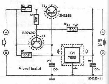
This power supply circuit utilizes a 7805 voltage regulator, which is a popular choice for providing regulated 5V output. The 7805 requires an input voltage that is typically higher than 7V to ensure proper regulation. The circuit's design incorporates T1 as a current limiting device to protect against excessive current draw. When the voltage across R2 and R3 reaches the threshold of 0.6 to 0.7 volts, T1 switches on, effectively cutting off the base current to T2. This action prevents T2 from turning on, which would otherwise allow more current to flow through the circuit.
The arrangement of resistors R2 and R3 is critical, as they are responsible for monitoring the voltage levels and ensuring that the current remains within safe limits. The voltage divider formed by resistors R3 and R4 is essential for establishing the correct biasing conditions for T2, allowing it to function properly within the circuit. This configuration ensures that T2 only activates when the voltage levels indicate that it is safe to do so, thus providing an additional layer of protection for the entire power supply circuit.
Overall, this circuit is an efficient solution for applications requiring a stable 5V power supply with built-in current limiting features, making it suitable for various electronic devices and projects.This power supply electronic circuit is a high current 5 volts power supply circuit that use a 7805 voltage regulator and some classic electronic components. T1 acts as a current limiter. Once the voltage on R2 + R3 is greater than 0. 6 0. 7 V, the transistor opens, which will reduce to zero the current in the base of T2. Voltage from which enters i n operation the protective circuit is given by the sum of drops voltage on the R2 and R3. Resistors R3 and R4 form a voltage divider on T2. 🔗 External reference
Related Circuits
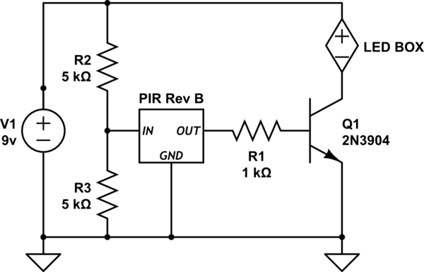
Activate a "black box" of LEDs (operating at 8-9V) when a motion sensor is triggered. The challenge is that the output from the PIR sensor is only 3.3 volts. The schematic provided requires several corrections. Firstly, using a resistor...
Although the 78xx series of voltage regulators are available with different current outputs, you can boost the available current output with this circuit. A power transistor is used to supply extra current to the load, maintaining a constant voltage....
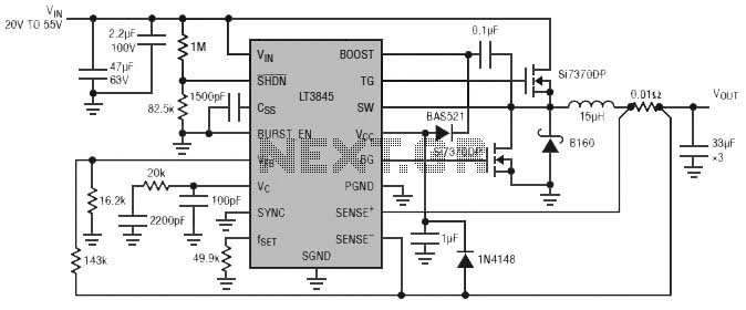
Burst Mode operation maintains high efficiency at light loads by reducing IC quiescent current to 120 µA. Light load efficiency is also improved with the reverse inductor current inhibit function, which supports discontinuous operation. Additional features include an adjustable...
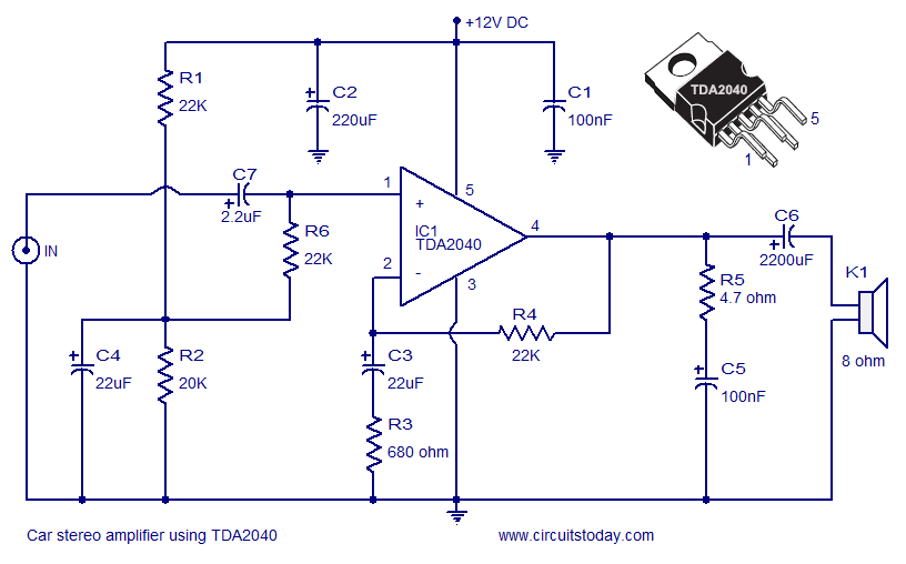
A car stereo amplifier circuit utilizing the TDA2040 is presented here. The TDA2040 is a monolithic integrated audio amplifier that functions in Class AB mode. This integrated circuit features built-in short circuit protection and thermal shutdown capabilities, and it...
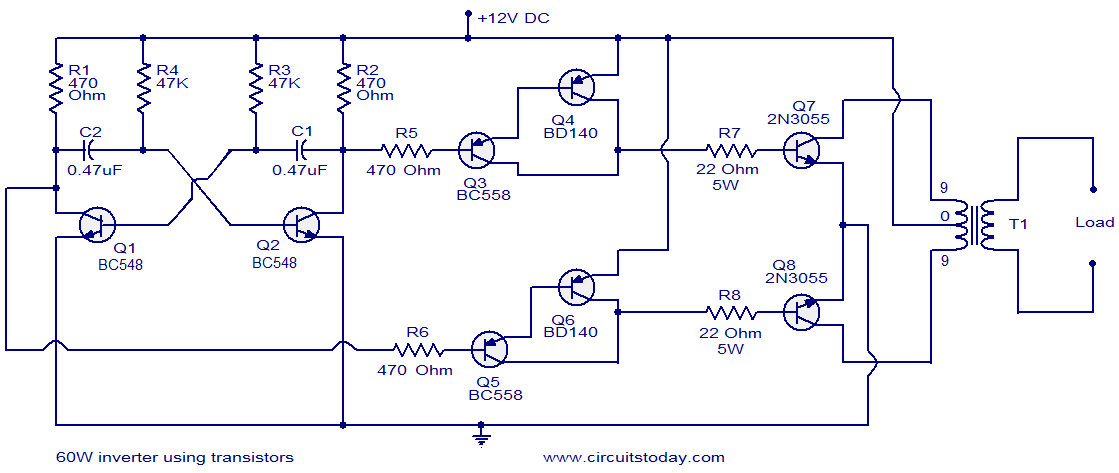
This circuit diagram illustrates a fully transistorized inverter capable of driving loads of up to 60W. Transistors Q1 and Q2 create a 50Hz astable multivibrator. The output from the collector of Q2 connects to the input of a Darlington...
The main feature of this power supply is its selection of outputs at standard fixed voltages commonly used in electronics. Since the outputs are fixed, there is no need to worry about voltage correctness; simply plug in the wire...