
Increasing Regulator Current

The circuit described utilizes a 78xx series voltage regulator, specifically the 7812, which provides a stable output voltage of 12V. The 78xx series is well-known for its ease of use and reliability in various electronic applications. However, its current output is limited, typically to around 1A, depending on the specific model used.
To enhance the current capacity of the circuit, a power transistor is integrated into the design. This transistor acts as a current booster, allowing the system to supply higher current levels to the load without compromising the stability of the output voltage. The configuration typically involves connecting the transistor's collector to the output of the voltage regulator and the emitter to the load. The base of the transistor is connected to the output of the regulator through a resistor, which controls the base current and, consequently, the collector current.
When the load demands a current greater than 650mA, the voltage regulator alone cannot meet this requirement. At this point, the power transistor begins to conduct, supplying the additional current needed by the load. This mechanism ensures that the output voltage remains constant at 12V, even under varying load conditions.
Thermal management is crucial in this design. Since the power transistor can dissipate significant heat during operation, it is imperative to attach it to an adequate heat sink. This will prevent thermal overload and ensure reliable operation over extended periods. The heat sink should be selected based on the power dissipation characteristics of the transistor, which can be calculated using the formula: Power Dissipation (Pd) = (Vce * Ic), where Vce is the voltage drop across the transistor and Ic is the collector current.
In summary, the combination of the 7812 voltage regulator and a power transistor allows for increased current output while maintaining voltage stability. This configuration is suitable for applications that require reliable power delivery beyond the standard limits of the voltage regulator alone. Proper thermal management through the use of a heat sink is essential for the longevity and performance of the circuit.Although the 78xx series of voltage regulators are available with different current outputs, you can boost the available current output with this circuit. A power transistor is used to supply extra current to the load the regulator, maintaining a constant voltage.
Currents up to 650mA will flow through the regulator, above this value and the power transistor will start to conduct, supplying the extra current to the load. This should be on an adequate heat sink as it is likely to get rather hot. Suppose you use a 12v regulator, 7812. 🔗 External reference
Related Circuits
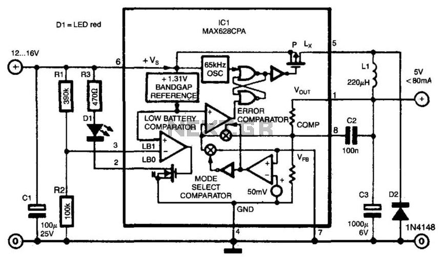
Switch-mode power supplies offer significantly greater efficiency compared to traditional power supplies. The switch-mode regulator described here achieves an efficiency of approximately 85%. It converts an input voltage range of 12 to 16 VDC into a stable output voltage...
This circuit is a variable output switching regulator designed for general-purpose applications. An LM105 positive regulator serves as the amplifier-reference for the switching regulator. Positive feedback to induce switching is derived from the LM105 at pin 1 through an...
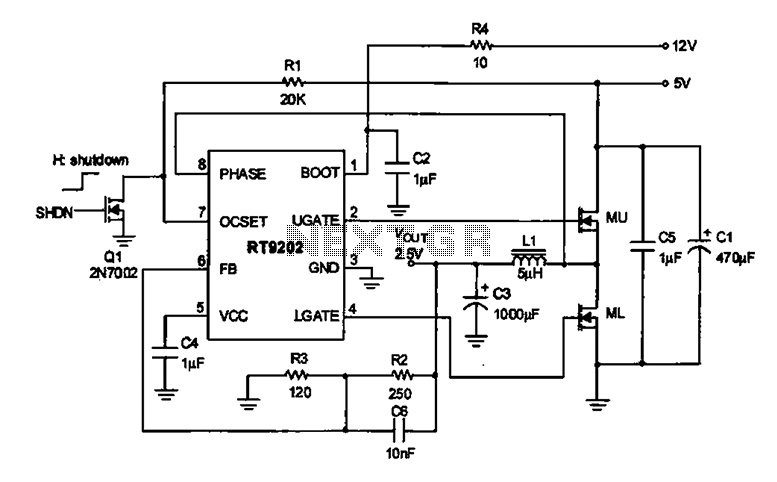
A 2.5V voltage regulator circuit is illustrated, which is part of a computer's motherboard. The circuit employs an oscillation circuit with the RT9202 control core chip, converting a 5V input supply into a regulated +2.5V output voltage, with the...
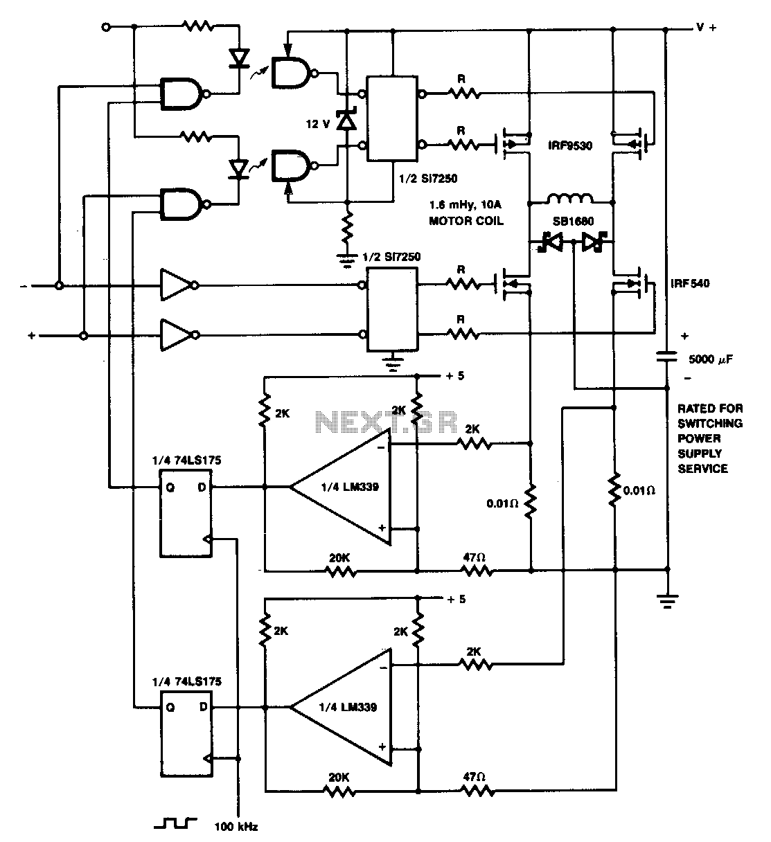
The p-channel devices are deactivated by current sensors when the coil current reaches 10 A. The operation resembles that of a switching-type power supply. Additionally, Schottky diodes and resistors are utilized for spike protection. In this circuit, p-channel MOSFETs serve...
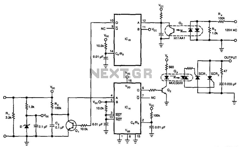
This circuit enables a 4-to-20 mA current loop to control an isolated SCR drive. IC1A and IC1B function as one-shot timers. Q2 detects zero crossings of the 120 Vac line, which triggers one-shot IC1B. IC1A causes Q1 to discharge...
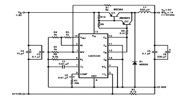
The schematic diagram below illustrates a 5V/1A Step-Down Switching Regulator utilizing the LM2524D Regulating Pulse Width Modulator (PWM). Additional parameters, PC board layout, stuffing diagram, and more information can be found in the LM2524D datasheet. The circuit design features the...