555 Timer IC for Square Wave Generator Application
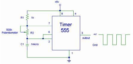
The setup for the Square Wave Generator can be initiated using a 555 timer IC as illustrated in the accompanying circuit diagram. It is essential to reference the pinout configuration of the 555 timer IC. An oscilloscope should be connected to the output of the 555 timer IC to observe the generated square wave. The oscilloscope allows for the measurement of the wave frequency, which can be adjusted by varying the resistance of the potentiometer.
The Square Wave Generator circuit utilizing the 555 timer IC is a versatile and widely used configuration in electronics. The 555 timer can operate in astable mode to generate a continuous square wave signal. In this configuration, the timer's output toggles between high and low states, creating a square wave.
The circuit typically consists of a 555 timer IC, resistors, a potentiometer for frequency adjustment, and capacitors for timing. The frequency and duty cycle of the output waveform can be controlled by the values of these passive components. The standard formula for calculating the frequency (f) of the output square wave is given by:
\[ f = \frac{1.44}{(R1 + 2R2) \cdot C} \]
Where:
- \( R1 \) is the resistance connected between pin 7 (discharge) and Vcc,
- \( R2 \) is the resistance connected between pin 7 and pin 6 (threshold),
- \( C \) is the capacitance connected between pin 6 and ground.
The potentiometer serves as a variable resistor, allowing for fine-tuning of the frequency output. By adjusting the potentiometer, the resistance value changes, thereby altering the timing intervals and consequently the frequency of the square wave produced.
The output from pin 3 of the 555 timer IC can be monitored using an oscilloscope. This connection enables visualization of the square wave, providing insight into its characteristics such as frequency, amplitude, and duty cycle. The oscilloscope also facilitates real-time adjustments and measurements, making it an invaluable tool for verifying the performance of the circuit.
In summary, the 555 timer IC in astable mode is an effective means of generating square wave signals. Through careful selection of component values and adjustments using a potentiometer, a wide range of frequencies can be achieved, making this circuit applicable in various electronic applications such as clock pulses, tone generation, and signal modulation.You can start to set your Square Wave Generator up using 555 timer IC through the circuit shown above. Find it match with the pinout of 555 timer IC. The osciloscope is then connected to the output of 555 timer IC in order to view the square wave. From the oscilloscope you can measure the wave frequency and verify it by varying the resistance in the potentiometer (source: utpa. edu ) 🔗 External reference
