
800 W soft start light dimmer
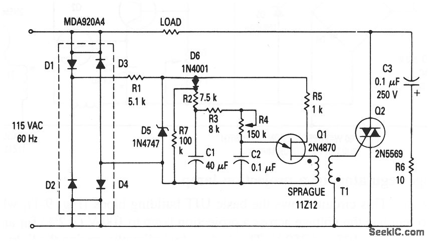
The UJT (Uni-Junction Transistor) circuit serves as a crucial component in light dimming applications, particularly where the management of inrush current is necessary to enhance lamp longevity. The soft-start feature is essential for mitigating the abrupt initial surge that can occur when power is first applied to incandescent lamps, which can lead to filament damage and reduced operational life.
In this configuration, the UJT operates in conjunction with a resistor-capacitor (RC) timing network, where R4 and C2 play pivotal roles. The charging time of C2 is determined by the resistance value of R4. As C2 charges, the voltage across it rises until it reaches the UJT's triggering threshold. At this point, the UJT turns on, allowing current to flow through the lamp. The gradual increase in voltage across the lamp results in a soft illumination that prevents the immediate, high-power draw associated with conventional dimmers.
The circuit's design ensures that the dimming effect can be finely adjusted by varying the resistance of R4, which directly influences the rate at which C2 charges. This allows for a tailored dimming experience, accommodating different lamp types and user preferences. Additionally, the UJT's characteristics provide a stable and reliable switching mechanism, ensuring consistent performance over time.
Overall, this UJT-based light dimmer circuit exemplifies effective engineering principles aimed at enhancing the functionality and lifespan of lighting solutions while providing users with a seamless dimming experience.This circuit shows the basic UJT building block (Fig. 9-1), which is used in a light dimmer with soft-start operation that applies current to the light slowly enough to eliminate high surges (high inrush current). These current surges, found in most cold-filament light dimmers, shorten lamp life. With this circuit, the lamp is heated slowly by a g radually increasing voltage so that inrush current is kept to a minimum. R4 controls the charging rate of C2 and provides the means to control or dim the lamp. 🔗 External reference
Related Circuits
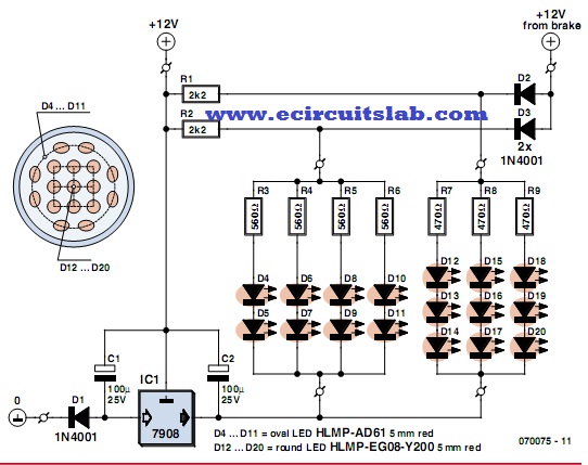
LEDs are increasingly utilized in motor vehicles, replacing traditional incandescent lamps due to their superior energy efficiency and extended lifespan. This article outlines a straightforward LED tail light specifically designed for motorcycles, scooters, and mopeds. There is a notable...
This simple circuit drives six LEDs in a "Knightrider scanner mode." Power consumption primarily depends on the type of LEDs used, especially if a 7555 (555 CMOS version) is utilized. The circuit operates by sequentially illuminating the LEDs to create...
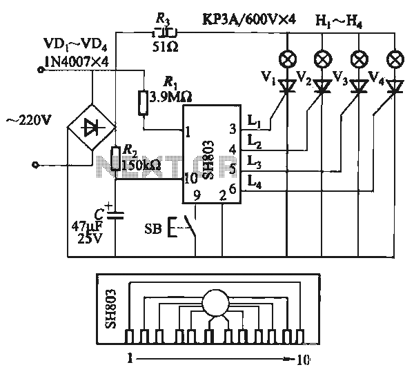
The circuit utilizes the SH803 flash IC, which can store eight different programs and offers various dimming options and light speed adjustments. A button is provided to trigger the control terminal SB on the 9-pin connector for program selection,...
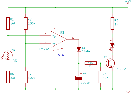
This electronic breadboard circuit for beginners in electronics activates an LED automatically when the ambient light level falls below a specific threshold. This circuit utilizes a light-dependent resistor (LDR) as the primary sensor to detect ambient light levels. The LDR...
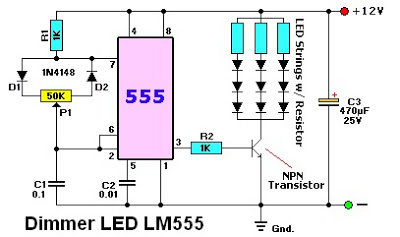
The LM555 timer IC can be utilized in various electronic projects, including the creation of an analog timer. According to the datasheet, the LM555 is versatile and can be adjusted to set timers based on specific requirements. The schematic...
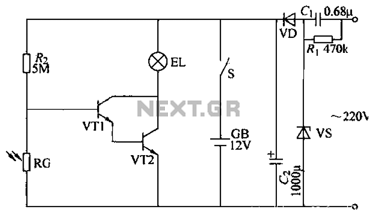
The power supply circuit features a step-down capacitor (C1), bleeder resistors (R), a Zener diode (VS), a full diode (VD), and a filter capacitor (G), along with switches and batteries (GB, SC). The light control circuit is composed of...