
LED Brake/Rear Light Specifically for motorcycles Circuit diagram

The schematic for this LED tail light circuit should include the following components: a power supply section capable of handling input voltages from 10.5V to 15V, a negative voltage regulator (7908) to stabilize the voltage at the chassis side, and multiple series resistors for current regulation. The LED configurations must be clearly depicted, showing the series and parallel arrangements of the round and oval LEDs, along with the necessary diodes for brake signal management. Each LED string should be labeled with its type and orientation to ensure correct assembly. The design should also incorporate protective features such as fuses or transient voltage suppressors to safeguard against voltage spikes, ensuring the longevity and reliability of the LED tail light system in a motorcycle environment.LEDs are used more and more in motor vehicles, replacing the standard incandescent lamps because they are more energy efficient and have a much longer life expectancy. In this article we describe a simple LED tail light that has been specifically designed for motorcycles, scooters and mopeds.
There appears to be a significant need among motorcycli sts for rear lights with LEDs, as evidenced by the many messages on this topic that turn up in various internet forums. The circuits that accompany these messages are often very rudimentary and therefore not very robust. After reading some of the literature concerning the use of LEDs in motor vehicles, it appears that the most common reason why LEDs still fail is the incorrect and/or insufficient use of series resistors.
In poorly implemented circuits there are often a number of LEDs connected in parallel which are all fed from a single series resistor. Because of small variations between LEDs, one LED can quickly give up the ghost. This causes an increase in current through the remaining LEDs and can easily lead to a domino effect, ultimately resulting in the failure of the entire circuit.
With high-intensity LEDs, a small variation in current is immediately obvious as a large variation in light output. This has to be taken into account when designing a circuit. This is important because when the engine rev speed goes up, the on-board voltage increases significantly.
It would appear that you were braking when you actually opened the throttle instead. LEDs need mainly a constant current. That is why most circuits choose to drive LEDs from a constant-current source. This circuit has been designed to operate both as a motorcycle rear light and as a brake light. This requires two different currents. Because the voltages measured on the author`s motorcycle varied from 10. 5 to 15 V and because two different currents are required for the total of 17 high-intensity LEDs it was not possible to use only one constant-current source. The idea was to turn the strongly varying DC voltage into a nice constant voltage first and then turn that into a constant current through a number of series resistors.
The problem that is highlighted in many forums is the fact that the signal for the brake light is a positive voltage. It would require a lot of work on the motorcycle to change this. That is why the decision was made for a de sign that regulates the voltage on the chassis side, with the aid of a negative voltage regulator, a 7908.
The disadvantage of this arrangement is that an additional chassis wire is required; normally the minus side of the lamps is directly connected to the chassis of the motorcycle. However, the advantage is that both the + from the rear light as well as the + from the brake light can be directly connected to the LEDs.
The lamp` con sists of a centre part with nine round, red, 5-mm LEDs (HLMP EG08 Y200) wi th positioned around that eight oval, r e d L E D s HLMP AD61 of 5 mm. The round LEDs D12 through D20 which have qui te a narrow radi ation angle are connected in series in sets of 3.
Three of the se strings` are connected in parallel and each string has its own series resistor. The oval LEDs D4 to D11 which have a wide radiation pattern are connected with two in series, so there are therefore four strings connected in parallel. These ensure with their wide radiation angle of 110 degrees that the rear/brake-light is also clearly visible from the side.
The oval and round strings are connected to the brake contact via diodes. When the brake is operated all the strings are presented with the +12V from the battery via the series resistors. The light intensity therefore depends on the current that flows as a result of the series resistor (and the voltage drop across the diodes).
When the brake is not operated, the LEDs strings are still connected to the positive voltage of the battery, but this time via additional re 🔗 External reference
Related Circuits
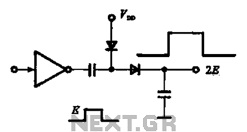
A pulse booster circuit is utilized to increase the pulse amplitude. The structure illustrated in figure (a) of the circuit can output a pulse amplitude that is twice that of the input. Figure (b) of the circuit can achieve...
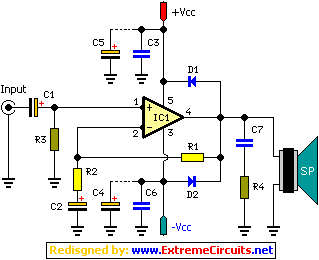
A 2 x 18W Hi-Fi Stereo Power Amplifier is designed using two TDA2030 integrated circuits (ICs). This amplifier features good input sensitivity, low distortion, stable operation, and comprehensive protection against overloads and output short-circuits. It can serve as a...
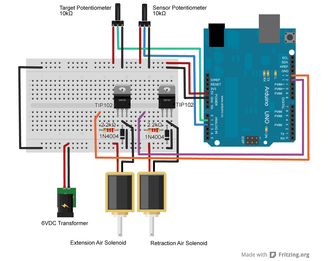
For an upcoming project, a pneumatic ram with a closed-loop control system was required to achieve precise positioning. Due to budget constraints, an off-the-shelf solution was not feasible, prompting the assembly of a custom system using an Arduino, a...
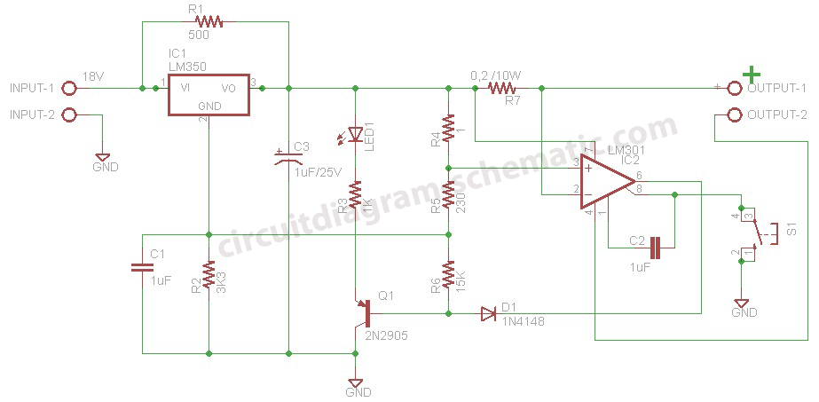
This is a battery charger circuit that has the advantage of automatically disconnecting the battery when charging is complete. The voltage sensor used in this circuit is the LM301 IC, which serves to disconnect the battery when the charging...
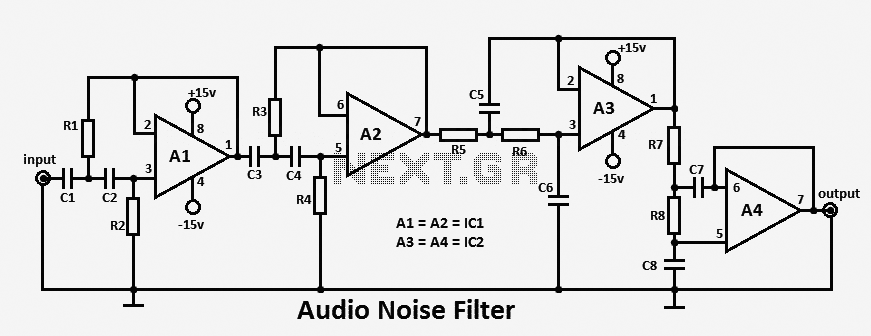
This audio noise filter circuit functions as a bandpass filter specifically designed for the audio frequency range. It effectively filters out unwanted signals that fall below or above the desired audio frequencies. The circuit comprises two filters: a low-pass...
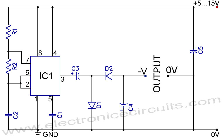
A 555 negative voltage power supply circuit can be created using a charge-pump configuration that incorporates a 555 timer, diodes, and additional components. The 555 timer is a versatile integrated circuit commonly used in various applications, including oscillators, timers, and...