
A 12 Volt Switching Power Supply
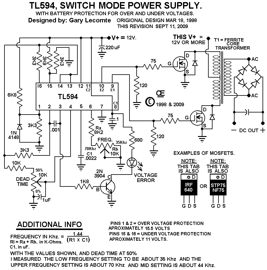
When constructing the transformer, it is crucial to select ferrite core material suitable for the intended frequency and power requirements, as not all ferrites are alike. The advantage of high frequency is that it requires fewer turns per volt, resulting in smaller ferrite core transformers compared to 60 Hz iron core transformers. However, this necessitates the use of smaller wire due to the skin effect, where higher frequencies cause current to flow predominantly on the surface of the conductor. For maximum efficiency at 35 kHz, a wire size of 21 AWG is recommended, capable of handling about 1.2 amps. At 70 kHz, a 24 AWG wire is suitable, supporting approximately 0.577 amps. To achieve high current flow with high efficiency, the use of Litz wire is advisable, which can be created by bundling multiple strands of insulated wire. Since high-frequency currents flow more on the surface, flat ribbon wire can also be employed, providing a larger surface area in a compact form. For instance, a ribbon wire measuring 0.010 inches thick and 0.25 inches wide can be comparable to a 12 AWG round wire, potentially efficient for currents up to 10 amps.About this Circuit This is a good Circuit for those persons needing to Boost or drop a voltage. The Output is High Frequency, but can be Rectified and Filtered to give DC Out. When Rectifying High Frequencies, You MUST use the Appropriate types of HIGH SPEED Diodes to handle these frequencies. Normal diodes WILL OVERHEAT and Burn out. This Circuit is based on a TL594 Integrated Circuit. And I have designed it with an Auto Shutdown, If your 12 volt battery voltage goes too high or too low. This will help protect your Battery and Alternator. So if the LED is "ON", The "Circuit has Shut Down". It is capable of driving just 2 mosfets, or 4 (with 2 in parallel on each side), or 6 (with 3 in parallel on each side).
So it can handle "LOTS OF POWER". The output voltage is determined by the "Turns Ratio" in Transformer "T1", as well as the Input voltage to T1. The TL594 Circuit Board Must have a Supply voltage of between 11 and 15 Volts. However, The Primary Supply Voltage for T1, Can also be 12 Volts, or Any other Voltage you want. The Primary winding should be "Bifular" wound, so both winding are identical. The Output Power can be Continuously Adjusted from very low to Full Power by using the "DEAD TIME CONTROL".
If this circuit is Built According to the Schematic, the Frequency range will be aproximately 35Khz to 70Khz. About making the Transformer First Off, The Ferrite Core Material, MUST be Suitable for the "Frequency" and "Power requirements", of the transformer your attempting to make.
Not all Ferrites are the same. The Advantage of using High Frequency is Less Turns per Volt, Resulting in Quite Small Ferrite core Transformers, as compared to 60 Hz, Iron Core Transformers. The Disadvantage is the need to use Smaller Wire as the Frequency Increases. WHY, Because the Higher the Frequency, the Greater the "Skin Effect". (The Higher the Frequency, The More the Current Flows on and near the Surface of the conductor. ) To get Maximum Efficiency at 35 Khz, the Wire size should be a 21 AWG, But that is Only good for a Current of about 1.
2 Amps To get Maximum Efficiency at 70 Khz, the Wire size should be a 24 AWG, But that is Only good for a Current of about 0. 577 Amps. So to get High Current flow, at High Efficiency, you need to use "Litz Wire", or make your own, by Bundling numerous strands of an appropriate wire gauge.
(Each Strand MUST be Insulated from each other, so Use Enameled Transformer Wire. ) Since High Frequency Current Flows more on the Surface, It is also possible to use Flat Ribbon Wire. This type of wire offers consideraby more surface area in a smaller space. Such a wire may be only 0. 010" thick, but 0. 25 inch wide. And I believe that would be somewhat Equivalant to a 12 AWG, round wire and possibly efficient up to 10 amps.
🔗 External reference
Related Circuits
This circuit functions as an RF power amplifier designed to operate with a power supply capable of delivering 13 volts at a current of 10 amperes. Careful assembly of the power source is essential. It utilizes a shielded transformer...
This simple circuit provides a regulated output of 4.7 volts for charging a mobile phone. A USB outlet supplies 5 volts DC at 100mA, which is adequate for slow charging of mobile phones. Most mobile phone batteries are rated...
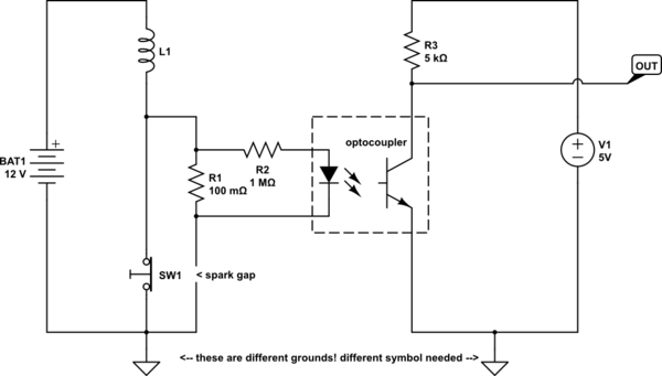
Construct a simple circuit that pulls a logic line low each time an automotive ignition coil fires. The initial idea is to connect the negative terminal of the coil to the base of an NPN bipolar junction transistor (BJT)...
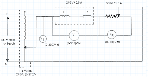
The parameters of the choke coil that will be measured using the three-voltmeter method include inductance and resistance, as all choke coils possess inherent resistance in addition to their inductance. Additionally, the quality factor and power absorbed by the...
This is an LM338-based power supply that is uncomplicated and easy to construct. It has been in use for an extended period without any issues. The circuit lacks a current adjustment feature, which has been addressed by incorporating an...
In this circuit we use the 2SK1058 and the 2SJ162 Mosfets. This could be avoided by a fairly simple bootstrapping circuit, but the improvement in maximum output may be just a fraction of a dB, depending on the supply...