
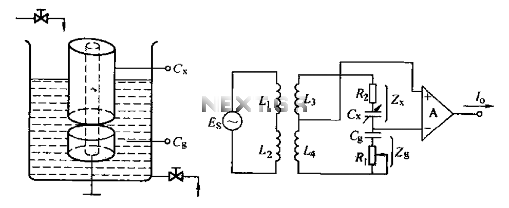
3 voltmeter method of measuring choke

The three-voltmeter method is a precise technique used for measuring the inductance and resistance of choke coils. In this method, the choke coil is connected in a circuit where the supply voltage (Vs) is controlled by a variac, allowing for fine adjustments to the voltage level. The choke coil, characterized by its inductance (L) and equivalent resistance (r), is subjected to a sinusoidal voltage source.
The three-voltmeter setup consists of three voltmeters: one measuring the voltage across the choke coil (VL), another measuring the voltage across the equivalent resistance (VR), and the third serving as a reference or additional measurement point. The voltmeter readings are critical as they allow for the calculation of the power absorbed by the choke coil and the quality factor (Q), which indicates the efficiency of the coil.
The equivalent resistance (r) is a crucial parameter as it encapsulates the losses due to the resistive nature of the coil's wire (copper losses) and the magnetic losses occurring in the core material (iron losses). By accurately measuring these parameters, one can derive the performance characteristics of the choke coil, which is essential for applications in filtering, energy storage, and power management in various electronic circuits.
The phasor diagram associated with this measurement technique visually represents the relationships between the voltages and currents in the circuit, aiding in the understanding of phase differences and the calculation of the quality factor. This comprehensive approach ensures that all relevant factors affecting the choke coil's performance are considered, leading to accurate and reliable measurements.The choke coil parameters we are going to measure in this 3-voltmeter method are - the inductance, resistance as all choke coils have inherent resistance in addition to their inductance. We also measure the quality factor and power absorbed by the given choke coil. A given choke coil is usually represented by a pure inductance (L) in series with e quivalent resistance (r). This equivalent resistance takes into effect the iron losses in the core of the choke coil and the inherent resistance of the choke coil. 3-Voltmeter method and 3-Ammeter method are two of the best ways to measure these two parameters. Thus the equivalent resistance accounts for the copper loses in the choke coil and the iron loses in the iron core.
Supply voltage `Vs` can be varied by means of the single phase variac. VR and VL are the voltmeter readings across the resistance and choke coil. The phasor diagram for the measurement of choke coil parameters by 3-voltmeter method is as shown below : 🔗 External reference
Related Circuits
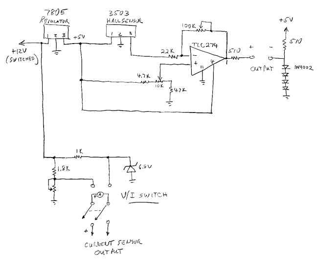
The sprite, which is experiencing an additional electrical load from an electric cooling fan, is barely maintaining battery charge. To address this issue, an electronic voltage regulator is planned; however, monitoring the charging process is essential before making any...

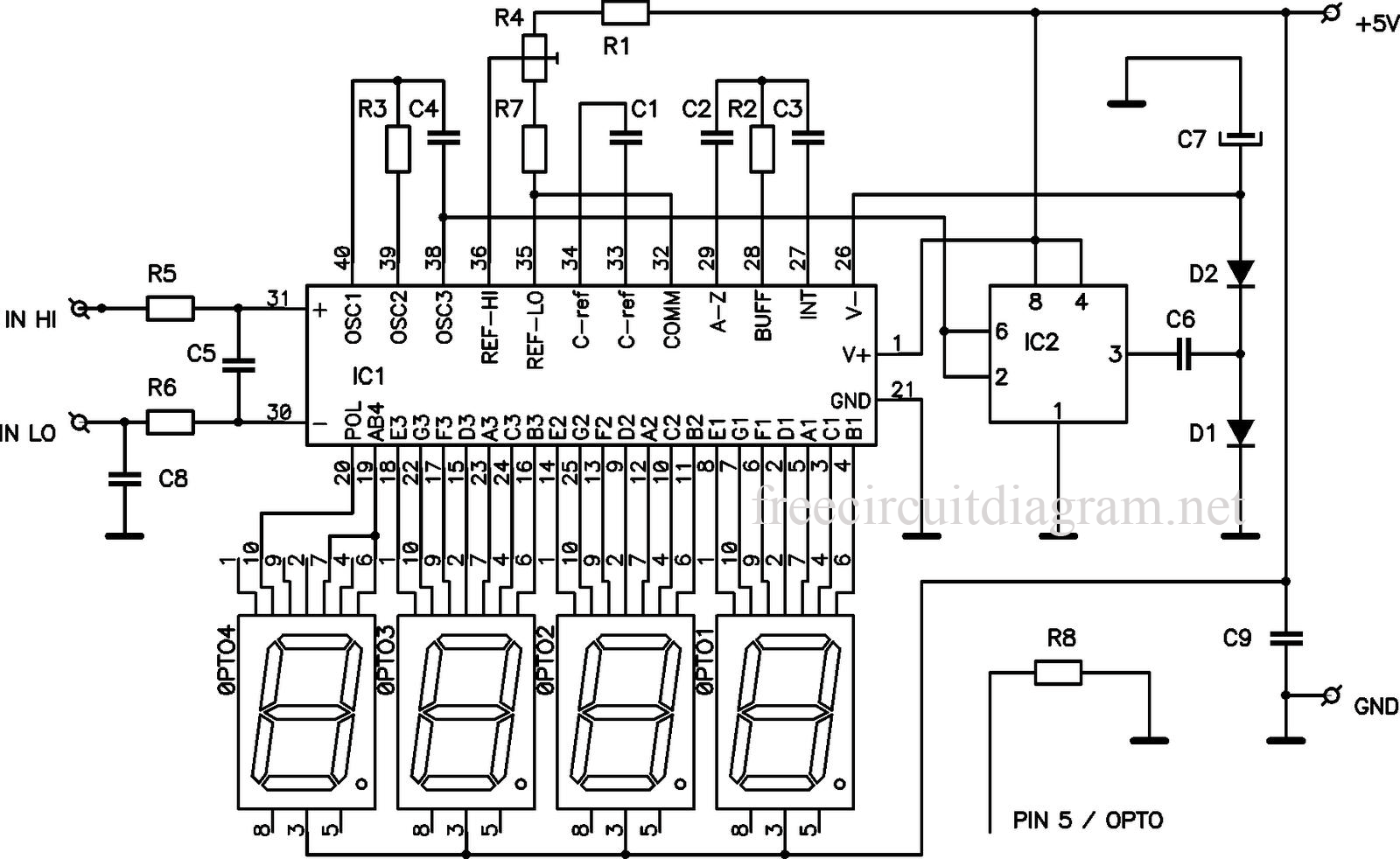
The frequency meter described not only serves its primary function but also allows for the measurement of inductance in various coils, resonant frequency of circuits, and capacitance of capacitors. The schematic diagram of this combined device is illustrated in...
This circuit is a digital voltmeter diagram featuring an LED display. It is designed for measuring the output voltage of a DC power supply. The voltmeter incorporates a 3.5-digit LED display along with a negative voltage indicator. It is...
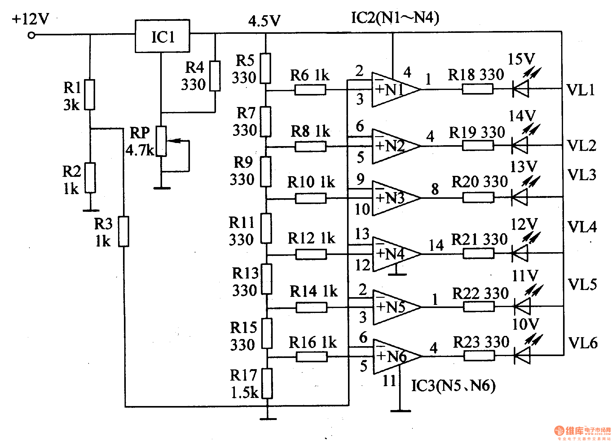
This document introduces an LED car voltmeter constructed using the op-amp LM312 and LED components. It is designed to display six voltage levels ranging from 10V to 15V, with each level representing a 1V increment. The working principle of...
The capacitance change in a capacitive sensor is directly converted into electrical parameters, which are then unified for signal transmission, processing, and display. These electrical parameters can be categorized into resistive, capacitive, and inductive types. This explanation focuses on...
The A2N3819 FET provides a solid-state volt-ohm meter (VOM). The 2N3819 functions as a cathode follower within the VOM configuration. The bias offset, also known as meter null, is achieved using resistors R14 and R12, which are responsible for...